Joule thief problem and a question?

mrk442

Newly Enlightened
Joined
Dec 1, 2007
Messages
42
First the problem..

So i am building a joule thief.

I am building the ultra simple one that only has the two inductors "coils" 1k resistor and the npn22222 transistor

the problem i have is that when i wire it up to the battery it will flash the LED when it is first connected but that's it then no light if i life the wire and put it back over and over it blinks every time?

I built it to spec and have tried a hand wound coil and i also tried using some 470uh inductors in case there was a problem with my windings...no luck

it does light so i have to assume its working for a microsecond but then nothing..


any ideas?


also is it possible to build a joule thief type circuit that would be capable of putting out say higher amperage then the standard one.. say 200-350ish?

can these little circuits be run in parallel or do they not work that way?

i thought maybe if i put a diode on the output from each circuit to the led to limit any reverse flow and the effect it might have on them..

the tried and true basic original joule thief is a really simple circuit
joule7.jpg


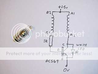
as can be seen on this site... http://www.bigclive.com/joule.htm

thanks for the idea though!
 

Mr Happy

Flashlight Enthusiast
Joined
Nov 21, 2007
Messages
5,390
Location
Southern California
I've read about it but have never built one myself. Did you wind the coil exactly as instructed, and did you make sure to keep the polarity correct on the coil terminals (i.e you must connect the coil terminals exactly as shown and must not mix them up)?

I don't know if the 2N2222 transistor is an equivalent substitute for the BC549, but I suspect given this simple application that it is.

If at first you don't succeed, try, try again. When things don't work out, it is always best to go back to the start of the instructions and repeat each step, checking each one with extra care to make sure you are following exactly and didn't make a mistake somewhere. If that doesn't work, try substituting components like the transistor or LED for a different one to see if that helps. You may have an unsuitable or faulty part.
 
Last edited:

mrk442

Newly Enlightened
Joined
Dec 1, 2007
Messages
42
I actually tried a hand wound inductor and thought i wound it right but i could not get any light at all using that and i know i had the polerity right as i checked with my meter? I also tried using two ready made inductors to see if my winding was the problems I used 470uh inductors which might be a little large for this application as i think the target is around 300uh

I don't know what it would cause if they where in fact to large.. and i know the npn22222 should work from reference material i have read elsewhere.

thanks for the idea maybe i will try the hand wind again to see if i just messed up.. or a smaller inductor..

it did light the led so i must have a semi functioning circuit since it will not light it with just the AA..

i tried a coulple of led's also.. red, blue, white, cree P4.. i get the same quick flash on bat connect with them all..
 

Mr Happy

Flashlight Enthusiast
Joined
Nov 21, 2007
Messages
5,390
Location
Southern California
A pair of ready made inductors will not work in this circuit since it is actually a transformer you need to create. Two separate inductors will not do the same job as a transformer because they lack the magnetic coupling between the windings that a transformer has.

I recommend you try again, winding the coils onto a ferrite bead exactly as described in the instructions, and make sure to identify the ends A1, A2, B1 and B2 as shown in the picture and connect them to the right parts of the circuit. That part is critical. If you connect either of A1 & A2 or B1 & B2 the wrong way round the circuit will not work.
 

mrk442

Newly Enlightened
Joined
Dec 1, 2007
Messages
42
interesting and good to know i will give it a shot.

i got the idea from looking at the kit one of the sites is offering.

the instructions for the kit at joulethief.com

I now notice it only had 1 inductor and is in essence a differant circuit.. thanks again


ohh and is there anyway to build a more powerful one? efficiency is not really my concern? can they be run in parallel?


1. Trim the board to the final size you want before assembly. The board may be sawn, sanded or filed to shape. It is designed to be round should you want, a bit less than the diameter of an AA cell (will fit inside common plastic pipe).
2. Hold the board so that the square pads for the battery connection are on the right, with plus above minus as shown above.
3. Install the 470 uH inductor (looks like a resistor) next to the input pads, spread the leads on the back side to hold it in place until soldered. No polarity concerns.
4. Install the two transistors as shown, watch the flats as they determine polarity. Spread the leads again to retain the parts until soldered.
5. Install one of the 1 K resistors (Brown, black, red, gold) and the .001uF cap (looks like a match head) above the LED mounting area as shown, again no polarity concerns.
6. The other 1 K resistor goes next to the LED on the left side, the 2.2 K (red, red, red, gold) outside that on the edge as shown, again spreading the leads on the back side.
7. Solder all components in on the back side, trim the leads.
8. Install the LED. It can be put through either side and mounted flush to the board or elevated to provide a number of options. Just be sure to watch the polarity, the longer lead goes to the round pad, the positive (shorter lead, with the flat on the rim) goes in the square pad no matter how the LED is mounted. Solder and trim the leads.
9. Connect the power leads to the square pads. The leads can be brought in from either side. Solder and trim as necessary.
 

Mr Happy

Flashlight Enthusiast
Joined
Nov 21, 2007
Messages
5,390
Location
Southern California
I'm not sure what instructions you have posted, since they don't seem to apply to the joule thief site you linked to. What is their relevance?

Yes of course it is possible to build more powerful circuits, but they are usually more complex. This general kind of circuit is called a boost converter since it boosts the battery voltage to a higher output voltage. Powerful ones are usually built around a custom IC that contains all the complex electronics except for an inductor and a capacitor.

You can buy ready made boost circuits for driving LEDs at high power from all sorts of sources that you will find referenced if you browse these forums.

Bear in mind that the "joule thief" is designed purely for interest and education. You should concentrate on at least getting it to work before worrying about possible increases in performance. I don't know that such a simple circuit has many possibilities for higher power.
 

mrk442

Newly Enlightened
Joined
Dec 1, 2007
Messages
42
the instructions where from anouther site www.joulethief.com i read them while putting together my parts list and noticed they used a ready made inductor for their kit.. I didn't even notice however that the kit differs radicly from the original joule thief :)
 
Last edited:
Top