SSC Acriche 110VAC 4W - - photos - -

Stage X Tuning

Newly Enlightened
Joined
Apr 29, 2008
Messages
19
I did a search but I have not found anyone that Tested one for a longer period of time. I bought 2 of them and wired one up and the LED with its PCB Heat Sink gets really hot. Looks as if the SSC P7 takes much longer to get as hot. What have you used to Heat Sink the Acriche? active heat sink?

AW3211-01LE-W2SYAC

AW3211_01.jpg


AW3211_02.jpg


AW3211_03.jpg
 
The resistors on the MCPCB are buring more than 1.5W at 40mA which could be one part the extra heat question.


space
 
Looks like each large die is 12 smaller ones (probably in series). It looks like two dies are connected in series, and each set of two dies in series is used for one polarity of the AC voltage (to keep flicker at 120 Hz instead of 60 Hz). With only 24 dies (~77V total assuming each has a Vf of 3.2V) that explains why the resistors get so hot. The resistor on average must absorb the 40+ volts between the LED Vf and the line voltage.
 
Rethinking, the total power input is ~4.4W (40 mA @ 110V) regardless of where it goes. The LED is transforming some to radiation, but most is transformed to heat. The heatsink getting hot just tells about how well/bad it is at dumping the heat to its surroundings.

space
 
My thoughts on these was one pair of dies was wired one way, and the second pair the opposite way.

That way at any given time one pair would light and the other would be off. They would flicker but in theory should produce a decently steady output.

Just a theory.
 
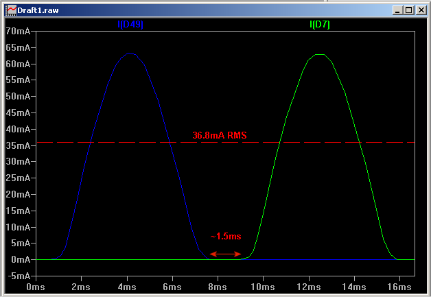
I did a quick simulation of two antiparallell strings of 24 Nichica NSPW500BS LEDs with 2x510 ohm series resistance and a 110V/60Hz supply.

acriche%20sim%20scem.png
acriche%20sim.png

The blue and green line illustrated the current going through each string of LEDs. Estimated RMS current is 36.8mA, not far from the 40 mA of the Acriche.
 
I dont see any flickering (only if you wave the led around youll see the flicker) ill have to check and see what is putting out the heat. The black wire is covering another resistor and im not sure why they have a cap. next too the resistor. ill get another photo of the board with out the wires to show you guys.
 
471= 47*10^1 = 470 ohm
511 = 510 ohm, if the two are in parallell (abit hard to tell from your pictures then 510/2=255 ohm.
Cap...could it possibly be an inductor?


space
 
I had a thought earlier today. I couldn't post it because either the CPF was slow, or my internet connection was messed up. :crazy: Now, I must have missed the details on how this unique emitter works, but I had a couple of ideas.

First of all, I am curious if this Acriche was a white emitter. It looks like a bare, but textured die, but the typical phosphor layer is missing. Is this the work of quantum dots? How about a thin ceramic substrate on top like what Lumileds are planning to use?

Looking at the last picture by the OP, I noticed that the current spreader traces on the top surface of the die were discontinuous. I had two ideas. Please tell me if they are crazy or if I am way off...


Current spreaders are usually applied on the die at specific distances apart to spread the current evenly over the die. If the distances are too far off, then you will get "dim" areas because that area is receiving less current.

So, does that mean that the single die has many regions that are wired in a series fashion? If so, then between each trace gap, there is a voltage drop due to what is required by the die material to be energized and release photons (Vf). With enough gaps, there will be a larger forward voltage (closer to ~110V?). Maybe on the underside of the die, there are strategically placed traces (like the rear of a Rebel emitter using flip chip dies), or just more current spreader traces. These alternate (or not) to ensure that current will continue to flow. For example, I will try to show you using a diagram. Imagine a cross section of the die. There are traces on the top, and maybe traces on the bottom. I know that current can only travel in one direction, but I am just throwing out something that could make sense maybe...
Code:
 _   _   _   _ <traces (top and bottom)
| |_| |_| |_|   <current flow?

or
 _   _   _   _ <traces (top only?)
|  \|  \|  \|   <current flow?
If this idea works, then i have a second idea. Can the LED die material ever conduct electrons in the reverse direction? Can they make dies with a alternating or reverse doped construction? Could AC be fed to each die (making it a series-parallel wired emitter) in a away where some regions of the die light up when placed in one polarity, then they switch over to other regions when the polarity is switched?

Lets say that these "regions" are wired in series. Could each die have a forward voltage of almost 50V so that the 120V model is wired in series-parallel, and the 220V model is wired only in series. The Acriche came in four models (100V, 110V, 220V, and 230V), so could the difference between each two groups (100/110V and 220/230V) be the selection of resistors? The picture in the OP's post shows that the dies are definitely wired in series-parallel. The bond wires in each corner are bonded to the same bit of metal (to be wired to the power leads).

Does this make sense? I am just trying to figure out the discontinuous current spreaders. I remember an older thread (no link) where someone took a picture of the Acriche emitter while lit up. It looked as though there were a grid of dies, but maybe they were just lit up regions. What do you guys think? Jtr? I wish Newbie was still around...

-Tony


EDIT:
I wonder if the capacitor and resistor in parallel is working as a current limiter. However, the capacitor is very small, so I doubt it could be big enough to program the combo to create 40mA of current. The resistor value is small for this application, too. Maybe I do not know enough about this basic current limiting topography. I am just learning some basics from a reverse engineered LED night light and some AC mathematics.
 
Last edited:
I got a reading on the capacitor 4.99pF.

The 511 resistors are in parallel and the cap and 471 resistor are also in parallel.
 
There is already one very interesting thread about Acriche here http://www.candlepowerforums.com/vb/showthread.php?t=181350

the ACricie emitter i used doesnt look at all like the pictures in this thread? me thinks this is the new higher lm/w one.

and i cheated bigtime, i used all the dies of the led, but i didnt like the spiking that the ac would do, so i DCed it.

i have had a bar of 10x2 of them running for many months now, lights up my whole room on low (using ~20w), and on high its ~50W going through all of it and its way too bright on high. when in low mode i use 1/2 the led gates, in high mode its the polar opposite using the other half of the gates.

I have it on a motion sencor, so it doesnt stay on all the time, so i am pretty sure with the setup i have going with it, it will last about 20 years for my use. no more changing bulbs, and way less power than i was using previously in the same room.
the room was powered by 2x30w circle Florescent lights using ~70W total inc. ballast, but stuffed inside light shade items, the ACricie bar is stuck to the ceiling RAW. someday i am gonna put a difuser around it, but its pretty cool.

on the heat sinking issue , as was asked, mine came with the bases enameled, then thermal transfer stickey stuff, peel and stick. i peeled all that crap off :) sanded down to the metal of the base, and thermal epoxied it onto a aluminum channel spaced well apart from eachother 10-2x on a 8 foot bar.
 
Last edited:
I found a 4W GU10 110v LED "bulb" at walmart that uses the SSC Acriche! about $42+tax though. me = broke. and it was yellower than the one pictured at the top of this thread.
 
I just want to clear some misinformation in this thread:
The Acriche board has no capacitor, it is a small PTC resistor acting as a temperature/overcurrent fuse. If the PCB gets too warm it triggers and the total resistance rise to the value of the parallelles resistor. (For 230V this PTC have a resistance of 470 ohm while below +70°C, and the parallell resistor is 3 kohm).
With DC you will only be using half of the 136 dies (230V version). There are 68 pair (230V) of dies in series, and each pair are connected in anti-parallell.
Each die run 20mA (230V) current when active, but with AC it will only have 50% duty-cycle.
 
Top