LED driver idea -> now planning bulk board manufacturing

ahorton

Enlightened
Joined
Jul 22, 2008
Messages
715
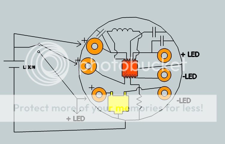
I have searched but not found. I'd love to know why this type of LED driver does not seem to exist:

3.0V-4.2V input voltage (1 Li Ion or similar)
The driver would be based around some sort of sensor that knows if the input voltage is more or less than 3.6V (or similar).
* When the input voltage is more than 3.6V, the LED current is limited via resistor or linear regulator (eg, AMC7135).
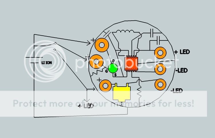
* When the input voltage is less than 3.6V, the LED is powered directly from the input (direct drive, probably through a Mosfet).

I have used AMC7135 drivers before but never like the way they have a 0.1V drop across the regulator once they fall out of regulation.

Also, can anyone point me towards some Mosfets (and other transistors) that operate well (turn on strong) at 3V? I have only used 5V ones in the past and do not think they would work well with voltage range of a single Li Ion cell.
 
Last edited:

MWClint

Enlightened
Joined
May 27, 2008
Messages
849
Location
Albany, NY
Last edited:

BillyNoMates

Newly Enlightened
Joined
Jan 16, 2009
Messages
144
Location
Bristol,UK
Re: LED driver idea

If you are interested in building your own driver, I can recommend the LTC3454 Buck-Boost driver chip from Linear Technology. I have used this in several lights I have made. It is ideal for driving LEDs at upto 1A from a single Li-Cell.
 

ahorton

Enlightened
Joined
Jul 22, 2008
Messages
715
Re: LED driver idea

I spent a few days thinking about the two options listed above and I like the look of the LTC3454.

Actually I like the look of the GD1000 (which I was aware of before) but I want about 50 of these drivers. So by the time I've spent US$1000 at the shoppe I think it would have been worth getting a stack of boards made up by some local pcb factory. At least that way I could have a heap of extras made up which I'd share with the cpf community at cost price.

So I'm going to see how much it will cost to get a bunch of one of these circuits made up:


drivers.jpg


The crude sketches are just to get a feel for everything that would go on the board. I think it could easily be done on a 15mm board.

The red chip is the LTC3454 and the yellow one is an AMC7135. I want to run two separate circuits for a 1A XR-E and a 350mA XP-E using an alternate action clicky switch (DX 12mm variety). By putting them on the same board I can save a few wires and make it all a bit neater. So I'd have the board permanently hooked up to the ground, and then apply + from the Li Ion to the appropriate circuit via the solder pad. The solder pads are orange in my sketches. I'll get holes drilled in them since I always prefer to solder wires through holes rather than on surface pads.

The sketch on the left shows two extra solder pads without holes. I like the idea of having 3 current settings for the LTC3454 circuit which can be chosen by bridging the gaps to the +ve pad with solder. (These go to EN1 and EN2). In practice though, I'll only want 1A so I'll probably go with the simpler circuit on the right.


Ignore this{
Of course I should probably throw in a mosfet (green) to look after the switch when I'm running the 1A circuit. It's rated for 1A but it will pull more than that when in boost mode.
driver_2.jpg

}


I realise the sketches are crude but I'm interested in any comments from people who know these circuits and chips better than I do. For example, how important are the capacitors?


I like the LTC3454 for the small number of extra components needed but let me know if there is an obvious better choice.
 
Last edited:

spencer

Enlightened
Joined
Jan 19, 2008
Messages
785
Location
Saskatoon, Canada
This project looks real good. I may be in for a couple because I like the efficiency of the LTC3454. If you can get them to us at cost then that would be sweet.
 

ahorton

Enlightened
Joined
Jul 22, 2008
Messages
715
:stupid: I understand if nobody ever wants to take me seriously ever again.

Scrap the last circuit I posted. A mosfet? What was I thinking? The LTC3454 goes into shut down if there is a '0' signal at both EN pins.

Let's try this one:

driver3.jpg
 

snarfer

Enlightened
Joined
Feb 21, 2008
Messages
241
Have you tried LTSpice? I think it will help you a lot to do a simple simulation. Since you are using a part from Linear anyway it will be very easy. Just start with their example circuit. If you don't know about it, look for it on the Linear.com website.

Also if you don't need to run both LEDs at the same time, then you don't need the AMC7135. Just program the torch mode for 350mA and the flash mode for 1A using resistors Riset1 and Riset2. Then hook up your switch to switch between the two LEDs and the two enable buttons.
 

ahorton

Enlightened
Joined
Jul 22, 2008
Messages
715
Yes I had considered using the two EN pins to give two different light levels but I hadn't worked out how to switch between the two LEDs. I'll have a think about it.

As for LTSpice, I had read about it but thought my circuit was too simple to learn much from it. Then again, this is a hobby and it is lots of fun, why not find a new toy to play with? I'll go get it.
 

BillyNoMates

Newly Enlightened
Joined
Jan 16, 2009
Messages
144
Location
Bristol,UK
Good to see someone else experimenting.

There are a couple of different ways of driving two different LEDs - you could for example use a MOSFET in series with each LED (N-type in the cathode branch of the LED). The gates could be connected with the EN pins - one set to 1A and one set to 350mA. That way the appropriate LED would be enabled for the selected drive. The MOSFETs will have some small loss in effeciency - especially for the low voltages you have available - make sure the 'on' resistance is sufficiently low at the minimum gate voltage for your application.

Good luck with the PCB - just be careful when designing the foot print for the part as it is very small. Best to follow the recommendation in the datasheet.

When it comes to soldering these guys down you are going to need a lot of patience......The small package of the LTC3454 is not very forgiving. It is essential that you use a hot-air tool (or hot-air tool in conjunction with a hot plate) and prefferebly solder paste. It is not possible to get a conventional soldering iron onto the pins as they are all under the body of the chip. The central pad is the ground connection and also heat sink for the chip. This needs a good connection to keep the device cool when running at full current.

It can be done - Iv'e build a boad with 10 of these suckers on - but it will frustrate you beyond belief if you don't have the right tools. It is too easy to cook the driver or board (the tracks for the pins are narrow and easily come away from the board substrate with heat) if you are not careful.
 
Top