
Torchaddict
Newly Enlightened
- Joined
- Jan 9, 2012
- Messages
- 121
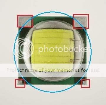
Are these squares (in red) conductive? It would seem that there are +/- connections (another forum member pointed this out to me judging from the darker electrical pathway that can be seen underneath the first PCB layer), but I can't seem to get a low resistance measurement from my multimeter. Are they just labels for reflow/mounting orientation? If I placed a reflector (in blue) would it short out the LED?
More pictures:
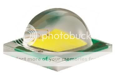
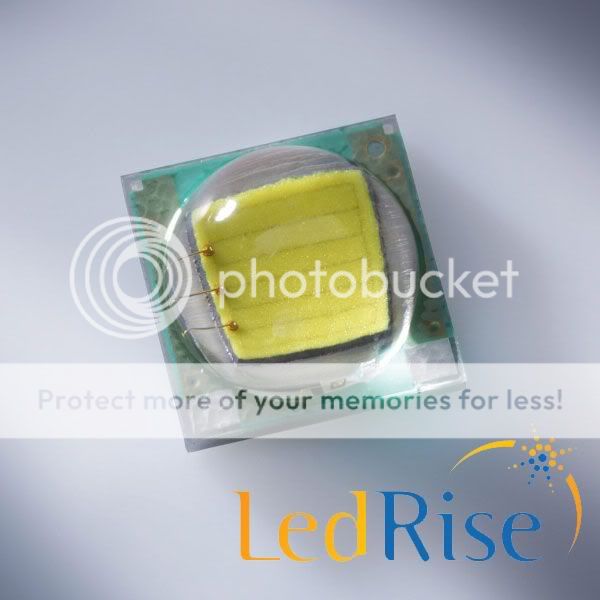
More pictures:
Last edited: