Need review of current control circuit for prototype build

capcouillon

Newly Enlightened
Joined
Sep 26, 2013
Messages
3
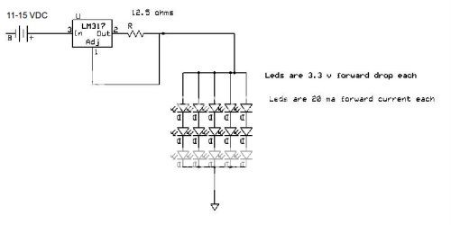
Have a project I want to pursue that requires some leds. Technically secure in the realm of hardware that requires taps and dies, but over my head when it comes to hardware that requires ic's and cazapitors... I can (more or less) read a schematic and stick the wires together, but the more esoteric aspects ususally evade me. As to the whys of this project, I will post more info if and when I manage to get a working prototype. Below I have posted the basic project parameters as well as a current control circuit I plan to use for ver 0.01. If y'all could do a quick skim and let me know of any glaring errors, or obvious revisions before the first build, it would be much appreciated. If all goes well, hope to build several hundred of these little dudes.

Power Supply: 11-15 VDC
Current Control IC Texas Inst LM317
Temperature Range: 0 - 50 degree C
Heat Dissipation: Very low, all electronics to be potted inside plastic container.
LED Type: Cree 503D-WAN (or similar) Vf= 3.2V Current= 20mA Millicandela Rating= 28150
Total LED: 15 in 3(s) x 5(p) array
Critical Factors: Cost and Reliability. Materials cost (LED+Control Components) vs Assembly time . Size of assembled control circuits.


ledarrayb-lm317-sm.jpg


TIA for your input and suggestions
Cap' Couillon
 
Last edited:

Steve K

Flashlight Enthusiast
Joined
Jun 10, 2002
Messages
2,786
Location
Peoria, IL
the basics are all correct. There are always finer details that can be discussed...

1. You might consider adding a couple of ohms in series with each LED string in order to ensure equal current sharing.

2. It wouldn't hurt to add a small capacitor (0.1uF or so) at the input of the LM317. especially if the battery isn't close to the LM317.

3. You didn't say what package you will be using for the LM317. I think you could avoid adding a heatsink if it is the TO-220. If it's a smaller package, such as the sot-223, you'll need to do something to help get rid of the heat (even though it's only a half watt or so).
 

capcouillon

Newly Enlightened
Joined
Sep 26, 2013
Messages
3
the basics are all correct. There are always finer details that can be discussed...
Thanks, the details are why am here...
Couple of changes/additions since my original post. Output resistor on the LM317 will be reduced to 12 ohms so I can use a std resistor.
(12ohm 250mw 1%tol) which will give me an output of 104mA or 20.8mA per string. Close enough for government work.

You might consider adding a couple of ohms in series with each LED string in order to ensure equal current sharing.

Resistance in parallel makes my head hurt.... While equalizing current sharing sounds like an excellent idea, if we are talking 2 ohms per string, how will this effect the required resistance on the output of the LM317. The only other issue is stuffing 5 more resistors into an already small (1.5 cubic inch) space along with the other components. Could be done if the guarentee of current sharing is important enough. Thoughts?

It wouldn't hurt to add a small capacitor (0.1uF or so) at the input of the LM317. especially if the battery isn't close to the LM317.
Have seen that noted in several circuit designs, but do not understand the function. Please to enlighten this humble one Master...
(Another bit to stuff in a very small and getting more crowded by the minute space)

I think you could avoid adding a heatsink if it is the TO-220.
Yes it's the TO-220 pkg but as this will be used outside I am going to have to pot the whole thing to keep out the weather, bugs, small children etc. Plan on using MG Thermal Conductive potting compound which ought to have enough thermal mass to act as a pretty good heat-sink in and of itself. (We shall see how that plan works out)

Tks again for your input and suggestions. Look forward to hearing back on my latest questions/confusions

Cap' Couillon
 

DIWdiver

Flashlight Enthusiast
Joined
Jan 27, 2010
Messages
2,725
Location
Connecticut, USA
+1 for everything Steve K says.

Your posted circuit (which I think is what you want) is for a 3S5P, or 3 series, 5 parallel design, not 5S3P as you suggested.

If you are potting in plastic, you might want to think about heat dissipation even in the TO-220 package. Depends on the thermal properties of the potting compound.

I pulled out my 1978 National Semiconductor Linear Databook (yes, that means the chip design is older than many of the people reading this post), which says the dropout voltage of the LM317 at 25C is around 1.6-1.7V at 100 mA. This means the input voltage must be higher than the output voltage by at least this much. Also, the LED string is driven at the ADJ voltage of the LM317. This is 1.2V below the output voltage.

So at 11V input you will not be able to maintain 9.9V output (3.3V times 3 leds). Adding a series resistor would make this even worse. I'd want to ensure 13V, maybe more, at the input.

And no, they haven't improved the LM317 in all those years. They may have improved the design, but they don't call it an LM317.
 

capcouillon

Newly Enlightened
Joined
Sep 26, 2013
Messages
3
@DIWdiver
Your posted circuit (which I think is what you want) is for a 3S5P, or 3 series, 5 parallel design, not 5S3P as you suggested.
(Face-Slap) Tks...Now edited in OP Orignal back-of-napkin sketch used the 5s3p and forgot to change.
If you are potting in plastic, you might want to think about heat dissipation even in the TO-220 package
Probably my reply to SteveK hadn't cleared the mod (still working on my 3'sees) when you replied to my OP. Planning on using MG-832TC to pot. Excellent thermal conductivity and by my calcs, should provide enougn thermal mass to sink the IC.
the dropout voltage of the LM317 at 25C is around 1.6-1.7V at 100 mA.
Tks, I know we are marginal at the low end of the given supply voltages, but one of the reasons to prototype this unit is to test some "real world" conditions... Would expect the typical low end voltage to be much higher under normal conditions, but if it gets too dicey, will just have to change the array configuration to get there. Even at low voltage, still have mucho amps available so we can fiddle something around til it works.

Tks again for the input both from you and SteveK... Time to order some parts and start building some stuff.
__________________

@The Mod Who Moved This Thread
While you may move this thread wherever you think it most appropriate (with no objections from myself), this is not a prototype for a flashlight build but rather another lighting project using LEDs. As I plan to post followups to the OP for general edification of the masses (good or bad results of prototyping), anyone who follows this design looking for a "flashlight" will be sorely disappointed by function and aesthetics. It does however use LEDs and associated driver circuts which is why I originally posted in the Beyond Flashlights > LED forum..... Just sayin'

With Respect,
Cap' Couillon
 
Last edited:
Top