Cooling questions and concepts

cpassuel

Newly Enlightened
Joined
Sep 6, 2014
Messages
8
Hello,

I'm thinking about crafting a dive lamp, or to mod a old broken halogen lamp and I have some questions about cooling LED (especially with COB LED) dive lamps .

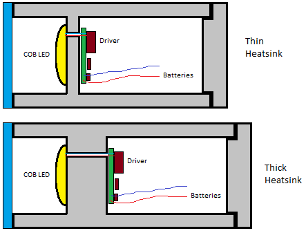
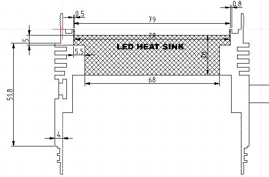
Which design is better for cooling ? Thin heatsink or thick heatsink (see picture below)? Of course it is probably related to led's power but is there a rule of thumb to choose a appropriate size?

With a thin heatsink design is there a risk that the LED warms the driver ?

Cooling.png


Does anodizing affects thermal transfer, so is it better put the led on raw aluminum rather than anodized aluminum (of course with thermal paste or pad between)?

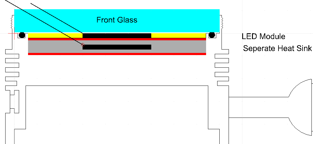
In Dive lightning library, Lucca Brassi posted an interesting concept of hole through metal enclosure for a better cooling, did someone tried it ?
cooling_led_through_metal_enclosure.png


Thanks
 

Packhorse

Flashlight Enthusiast
Joined
Nov 29, 2007
Messages
1,912
Location
New Zealand
If the heat sink is thicker it will take longer to heat up. But given enough time the LED could still over heat.

To keep the LED cool you need a heat sink with lots of surface area ( eg fins). Although this isnt such an issue in water since the water will conduct heat over 20 times batter than air.
 

cpassuel

Newly Enlightened
Joined
Sep 6, 2014
Messages
8
Yes, you have to maximize external surface of the lamp (with grooves for example) because water flow will cool the body's lamp (conduction). That's why fins inside the lamp are useless because there is no air flow.

I found a very interesting document with lots of examples about heat transfer
http://wwwme.nchu.edu.tw/Enter/html/lab/lab516/Heat Transfer/chapter_2.pdf

I found that anodizing is not good for thermal conductivity and depends how anodizing is done.
http://www.dtic.mil/dtic/tr/fulltext/u2/a191755.pdf
 

turbodog

Flashaholic
Joined
Jun 23, 2003
Messages
6,425
Location
central time
A hole through the light is a very good idea.

I would mount the driver on some double stick tape. It will help insulate it from the heat.
 

DIWdiver

Flashlight Enthusiast
Joined
Jan 27, 2010
Messages
2,725
Location
Connecticut, USA
If it's in the water, you don't need fins, cooling holes, etc. The water is SO much better than air, that it's staggering. I think the 20 times number by Packhorse is way too low. You can easily dissipate 20 watts/square inch in water with little temperature rise. At 1 W/in^2 in air, you have substantial temperature rise.

If you ever operate it in the air, it's a very different story. There, maximizing surface area is critical. However, it's possible to cut away so much metal that you don't have good heat flow to all that surface. If you notice, most fins on aluminum heatsinks have an aspect ratio (the ratio of length to thickness) of no more than 10:1 or so. That's a tradeoff between maximizing the surface area and minimizing the temperature differential across the heatsink.

In water, the tradeoff is very different. Since surface area is so much less important, the geometry of the heatsink becomes relatively more important.

I'm just kind of musing here, but imagine an aluminum bar 1 cm square, and 4 cm long. Put 10W of heat in at one end, and connect to a heatsink at the other end. There will be some temperature drop across the length of the bar. The geometry is very different in your light head, but you still have heat flowing from the source to the sink, and there will be some temperature differential.

The thermal conductivity of aluminum is about 200 W/m-K (watts per meter-kelvin, a kelvin being equivalent to one degree C). So the temperature across our bar will be

dT = P/c * L/A, where P is power, c is conductivity, L is length, A is area.

Converting everything to meters gives L=4 cm = 0.04m, and A=1cm*1cm = 0.0001m^2, and

dT = 10W/(200W/m-K) * 0.04m/0.0001m^2 = 20K, or 20 degrees C.

Now imagine ten of these arranged like spokes of a wheel, with the hot end at the middle and the cool end at the outside. This is like the plate your LED is mounted on, with heat radiating from the center to the edges.

So a plate 80 mm diameter and 10mm thick carrying 100W (10 spokes at 10W each) would drop about 20C. Less probably, because we'd fill in all the gaps between the spokes.

That's of course only a very rough approximation. But it gives you an idea of the numbers you are working with.

If you only have 50W and can afford 40C drop, then you can use a much thinner plate. If you have 200W and your plate is 150mm diameter, you probably want a thicker plate.
 

DIWdiver

Flashlight Enthusiast
Joined
Jan 27, 2010
Messages
2,725
Location
Connecticut, USA
Oh, about anodizing. Aluminum oxide (which is what the anodized layer is) has a much lower thermal conductivity than aluminum. However, the layer is so thin that it typically makes little difference when you run the numbers. That said, it is slightly better to use bare aluminum. However, you'll find that the surface finish and the thermal interface material you use will probably make much more of a difference than whether or not it is anodized.
 

lucca brassi

Enlightened
Joined
Feb 1, 2008
Messages
889
Location
US
Trick cooling holes in this that the directional cooling in key positions at the same time to decrease the weight of the housing . They replace heavy Cu inserts for better thermal transport !

Anodizing is at the thickest mode (hard anoization ) thick 60-80 * 10-6 m , fine grinding paper solves anodizing under led mount quickly without problems.

I would mount the driver on some double stick tape. It will help insulate it from the heat

in generall is better to not have direct contact of electronics with housing ( not just at divelights ) . ( condensation , short circuits , galvanic series , ..... )

But in some cases drivers measures surroundings temperature , get feedback and then controll itself output.
 
Last edited:

cpassuel

Newly Enlightened
Joined
Sep 6, 2014
Messages
8
Thanks for this detailed answer.
What happens when time goes on, the temperature differential will probably drop ?
 

DIWdiver

Flashlight Enthusiast
Joined
Jan 27, 2010
Messages
2,725
Location
Connecticut, USA
Temperature differentials as calculated are steady state. Assuming you start with everything at the same temperature (differentials are zero), once you turn it on the differentials climb rapidly at first, then more and more slowly approaching the steady state values. In theory, the steady state values are never actually reached, but are approached ever more closely. In practice however, the differentials will reach the steady state values after some time, then stay there.
 

DIWdiver

Flashlight Enthusiast
Joined
Jan 27, 2010
Messages
2,725
Location
Connecticut, USA
Okay, some numbers for anodizing.

Type III anodized aluminum has a thermal conductivity of 0.5 - 1.0 W/m-K. This compares quite poorly to aluminum, which is around 200 W/m-K. So it's 200-400 times less conductive. Sounds pretty bad, huh?

Well, a very thick layer of type III hard anodizing would be 150 microns. That's 0.150 mm. So pushing heat through that layer would be like pushing heat through a layer of aluminum 200-400 times thicker.

Let's consider the very worst case. 400 times 0.15 mm is 60mm. So that anodized layer is equivalent to an extra 60mm of aluminum.

More typical of Type III would be 80 microns, 0.75 W/m-K, equating to 21mm of aluminum.

Typical of a fairly tough Type II would be 20 microns, and guessing more like 0.5 W/m-K, equating to 8mm of aluminum.

Typical of a cheap Type II would be more like 4-5 microns, equating to like 2mm of aluminum.

Consider the case of a 20mm star, and 7W of heat. The temperature differential across the anodized layer under the star would be 67C for the extreme case, 24C for the typical Type III case, 9C for the tougher type II, and only 2C for the cheap Type II layer.

So if you have Type III anodizing, sanding it off before attaching your LED or star will likely make a big difference, assuming you do a good job and end up with a nice flat, smooth surface.

However, since Type III requires an expensive and messy process, I can pretty much guarantee that unless you bought a high-end light or had the anodizing done yourself at a reputable shop, you don't have Type III. If you bought an inexpensive light that's black and claims Type III hard anodizing, you've been lied to. Most of the crap coming out of China is cheap Type II.
 

clawnfish

Newly Enlightened
Joined
Nov 28, 2014
Messages
18
Location
Europe
What about this guys ? Do you think a design like this will be OK for 100Watt COB LED Module ? The part marked as Heat Sink is a separate part with 2cm thickness.
nVh9qJa.jpg
 

clawnfish

Newly Enlightened
Joined
Nov 28, 2014
Messages
18
Location
Europe
Hi Lucca,

If your response is about my above drawing, then , it is going to be Aluminium completely both the body and the heat sink. The LED module will be installed at the top and the driver circuit will be installed at the bottom side of the heatsink.

Do you see any problems with this kind of setup, considering it will only be used underwater.
 

cpassuel

Newly Enlightened
Joined
Sep 6, 2014
Messages
8
Lucca,

In your drawing, you say LED must be right over the water flow but not on metal. What do you mean by not on metal ? Do you mean to use some thermal pad between LED and heatsink or something else ?
 

lucca brassi

Enlightened
Joined
Feb 1, 2008
Messages
889
Location
US
I don't know i have something to overview but led is mounted on metal ,on thermal conductive grease and screwed in the heat sink .

Important is just to not drill threads in water channel and to keep chambers dry (I'll correct picture )

--------------------------------------------------------------------------------------------------------------------

on your picture i would use cu hollow core insert just under COB , surrounded with AL ( look on standard intel procesor heatsink )
 

DIWdiver

Flashlight Enthusiast
Joined
Jan 27, 2010
Messages
2,725
Location
Connecticut, USA
Thermally, the issue I see is that the joint between the heatsink and the body is going to be a substantial thermal barrier unless you machine a very close fit AND fill any gap or void completely with thermal compound. It would be far better if that were a single piece.

Mechanically, I'll warn you against using fine threads that will be exposed to water, as on what I assume would be your bezel ring that holds in the lens. Water can carry sand and other grit into the threads, which can then become impossible to unscrew. Go ahead, ask me how I found that out:mad:.

But I'm going to guess that you don't even need the bezel ring. It looks like you are planning on a lens that's about 8mm thick, so it's probably plastic (polycarbonate, I hope). Just cut an o-ring grove into the edge of the lens and let the friction of the o-ring hold the lens in place. My first light was like this, and I used it for two years with no problems until the battery pack gave out and I built a brighter and smaller light. It will save you one part, not to mention cutting two threads, one internal and one external.
 

clawnfish

Newly Enlightened
Joined
Nov 28, 2014
Messages
18
Location
Europe
Hi DIWdiver,
Do you think this separate heat sink can be an issue thermally even if it is used only underwater ( which will be the case)?

My first thought was also to have it a single solid piece but the COB I'm planning to use is 1.9 mm thick and if I have it as a single piece , I may not use a different led module which is thicker than 1.9 mm in the future. I don't have access to a lathe and I am
planning to ask for 2 heat sinks one with above dimensions and another a bit deeper to allow for led modules up to 6.5 mm from my friend.

You are right, there will be a bezel to keep the lens in place which is a 10mm glass. I cannot visualize what you suggested to keep it in place without a bezel. Can you explain it a bit more maybe ? :)

About the thin threads, I will change it to a wider, deeper 1.5 mm pitch thread which I hope will be better against sand particles.
 

DIWdiver

Flashlight Enthusiast
Joined
Jan 27, 2010
Messages
2,725
Location
Connecticut, USA
The issue with the separate heatsink is about getting the heat from the heatsink to the body. This is independent of whether it is in water. It's not unrelated, though, because in water you know that the body temperature is always low, while in air it can be much higher. This alters the importance of the problem, not the underlying issue. Are you sure it will never be used in air? Even for a little while?

Maybe plan for the thicker COB, and order only one design to handle both COBs. An extra 4mm of depth would affect your light very minimally, while the single-piece design would improve thermal characteristics greatly.

For the glass, imagine three layers:
Outer layer, 2mm thick, 50mm diameter
Middle layer, 2.5mm thick, 47.5mm diameter.
Inner layer, 5.5mm thick, 50mm diameter.

If you glue all these layers together, you have a groove on the outer diameter of the glued-up lens. Fit an o-ring into this groove and push the lens into the front of your light. The o-ring will be compressed between the ID of the light and the OD of the middle layer of the lens. The friction will hold the lens into the light.

I think 1.5mm is about the thread pitch of the threads on my light that locked up and I haven't been able to move since about the third dive. If I were to do it again, I'd try to get to at least 3mm pitch and use trapezoidal threads with greater ID/OD clearance.
 

clawnfish

Newly Enlightened
Joined
Nov 28, 2014
Messages
18
Location
Europe
Thanks for all the explanation DIWdiver. Now I understand how you fitted the glass but I am not as brave as you :) so I will use a bezel just in case. I will still have only one o ring inside the front part and the glass will sit on it and the bezel will press from above to keep it in place.

This is going to be a UW Video light so, other than testing for very short periods, it will never be used above water. Also the drivers I am planning to use provide temperature control so , ideally, if the temperature rises too high, the driver will lower the current or shutdown the light completely.

The threads of some chinese lamps I use have less than 1 mm pitch with a similar bezel design but their diameter is less than half of the below lamp and I never had any problems about sand particles/salt etc. with those. But for this one I will see if I can increase the thread size while still having enough space for at least 4 turns of the bezel ( and the battery compartment of course).

For the heatsink, then maybe I can use a single piece coupled with a thinner flat aluminium disc which is attached to the top of the single piece with thermal paste so if I need to use a different thickness led module , I can change only the aluminium disk Like the one below. What do you think ? The reason I am trying to have it like this is to have the front of the LED Module as close to the glass as possible to have the full 120 degree of light. Cyan part is the glass, yellow part is the LED Module, Gray part is the separate heatsink ,red parts are the thermal pastes in between and the unpainted rest is the whole body. Of course there will be one or two holes through the heatsinks for cables.Black rectangles shows the actual emitter on the COB module and the 2 lines going 30 degrees to the left show the 120 degree limit of the light spread. As you can see, if I put the led lower, some of the light will be hitting the bottom of the bezel ( not in this drawing).

v47V6sa.png
 
Last edited:
Top