
*** edit, added descriptions ***
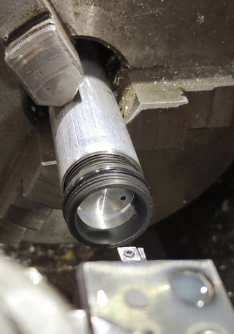
I made a threaded holder to (wait for it...) hold the middle part of the head. It has three aluminum parts: the lower shroud around the positive/ ground, the middle that holds the LED, and the front that holds the optics in place.
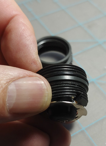
The head came apart with some help from a propane torch, it doesn't require much. This head has the domed optic at the very front, with it's ultra thin gasket where it would meet the metal, a rubber gasket and black plastic spacer ring, and finally the first TIR type optic that initially grabs the LED's output.
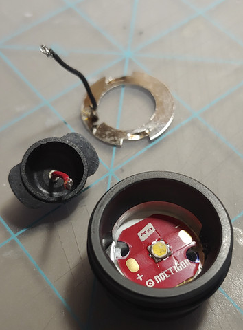
This is how the ground lead runs into the LED; under the plastic positive cup. This cup has wings that sit into slots in this middle aluminum part.
Here you can see the ground ring, and the positive cup. Simple, but they work for the amperages we're working with here.
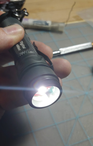
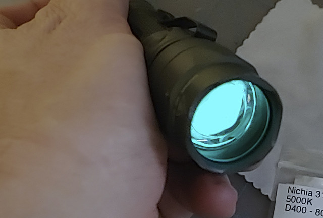
Mule test! successful, too
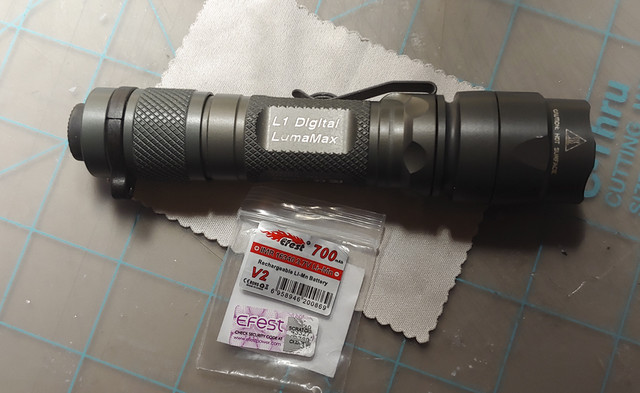
The 16340 fits nicely without its stickers
Glow strip in the head, because I like blue
~D
I made a threaded holder to (wait for it...) hold the middle part of the head. It has three aluminum parts: the lower shroud around the positive/ ground, the middle that holds the LED, and the front that holds the optics in place.
The head came apart with some help from a propane torch, it doesn't require much. This head has the domed optic at the very front, with it's ultra thin gasket where it would meet the metal, a rubber gasket and black plastic spacer ring, and finally the first TIR type optic that initially grabs the LED's output.
This is how the ground lead runs into the LED; under the plastic positive cup. This cup has wings that sit into slots in this middle aluminum part.
Here you can see the ground ring, and the positive cup. Simple, but they work for the amperages we're working with here.
Mule test! successful, too
The 16340 fits nicely without its stickers
Glow strip in the head, because I like blue
~D
Last edited: