Work on the stainless steel pieces has commenced. Since it is the easiest to produce, I've started with the head.
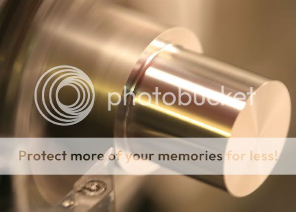
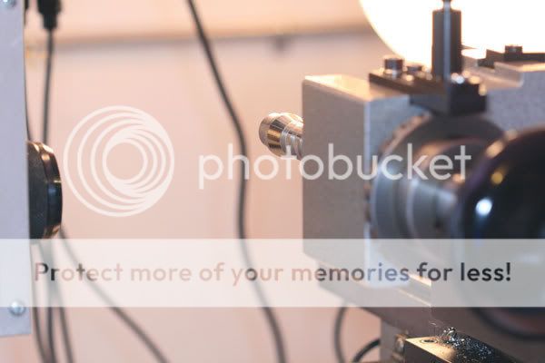
First, turn down the 1" stock so that a stub will fit my 19.5mm collet:
This is a tedious job, since it just involves the same operation over and over again until the right diameter is achieved. Then I face off the shoulder that the collet will butt up against:
Then a quick check to see that the collet does, in fact, fit:
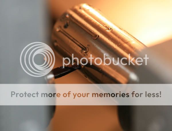
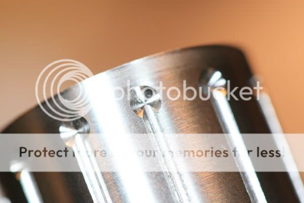
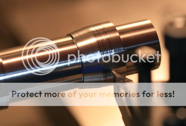
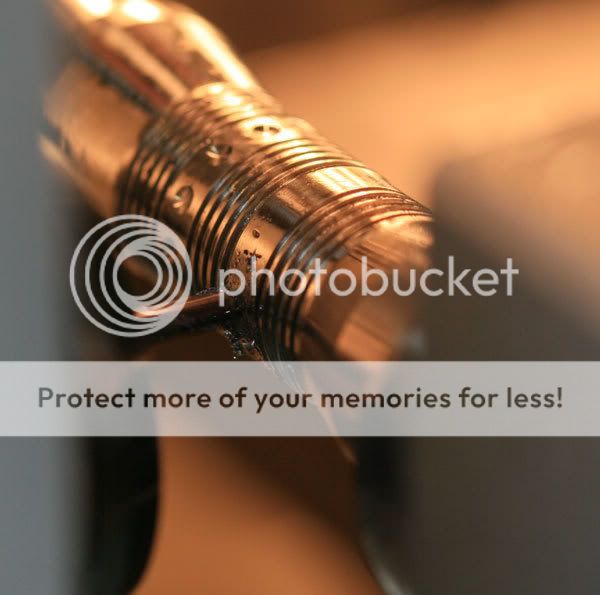
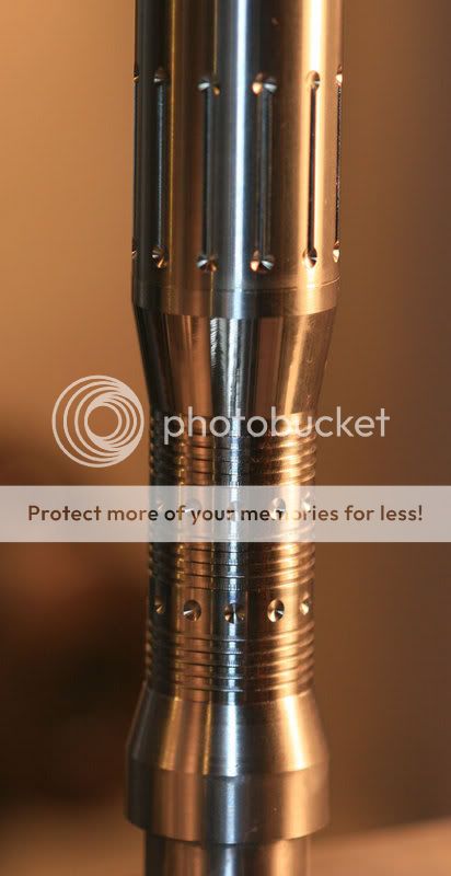
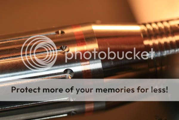
Next up was the milling of the lines and the dimples. The lines were to be milled with a 1mm diameter ball nose end mill, but the stainless steel proved too much for that small a tool--I broke five of them while trying to get some lines done. At first, I thought that perhaps I was taking too deep a cut, but changing to a lighter cut didn't help. Nor did slowing down the RPMS, using lubricant, etc. In the end, I moved up to a 1.5mm end mill and had no problem with that diameter.
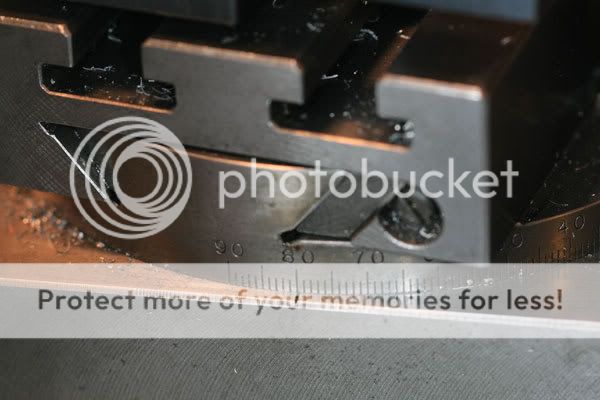
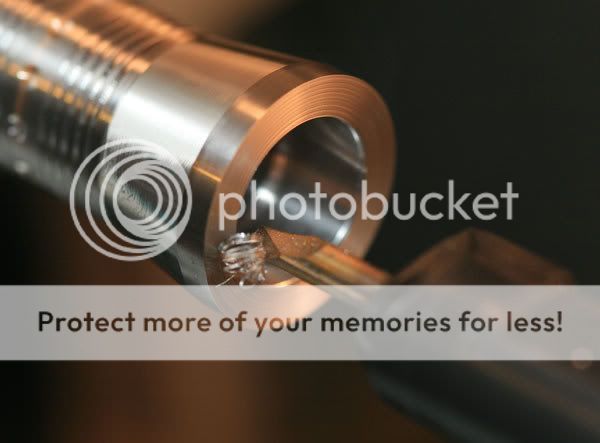
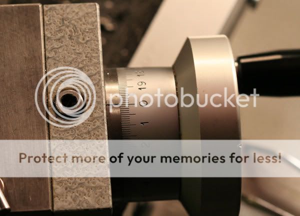
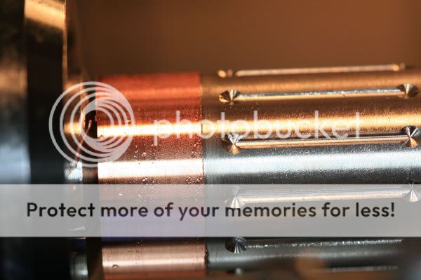
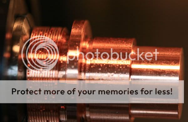
The dimples were done with a 4mm endmill; here's the final dimple and the end of an exasperating couple of hours:
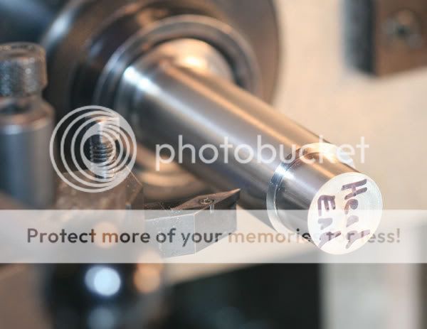
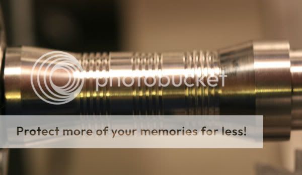
And after they were wiped off:
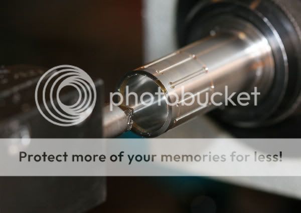
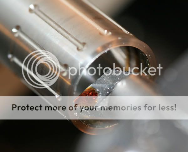
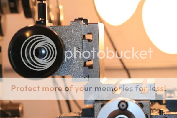
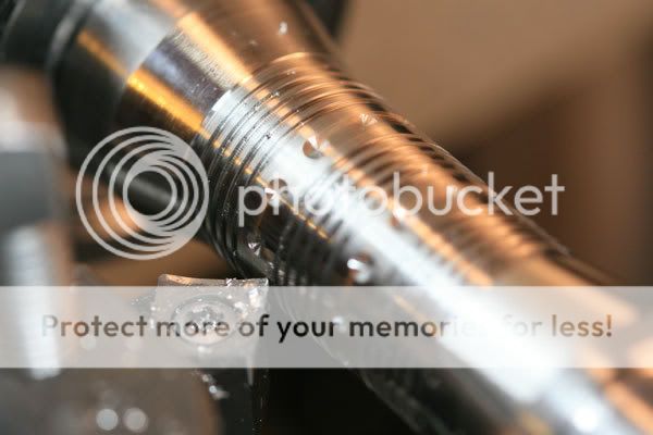
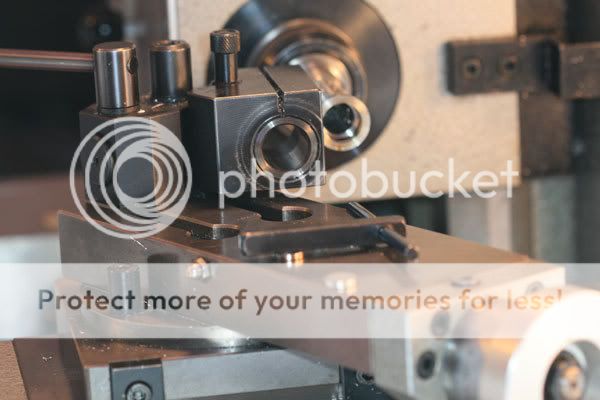
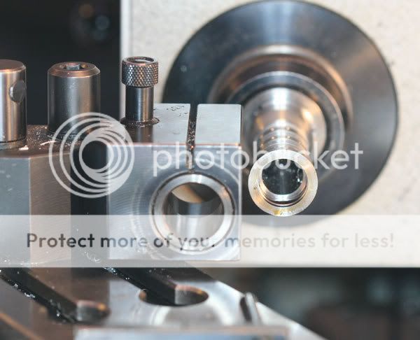
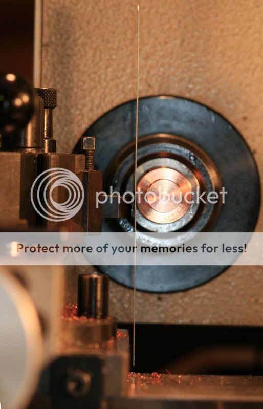
The head was then ready for drilling--I used three different drills to get close to the final bore diameter of 20.5mm. Here's the boring bar in action:
When boring, it's a good idea when the final diameter is reached to go back and forth with the boring bar to ensure that the spring in the bar is taken out and a smooth surface is obtained over the length of the bore. I used some Tap Magic for the final passes, although most of the boring cuts were done dry:
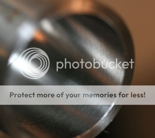
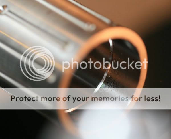
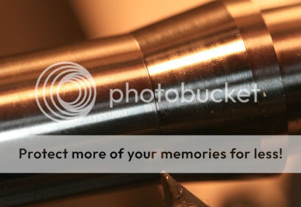
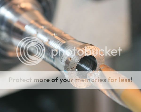
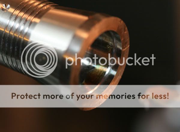
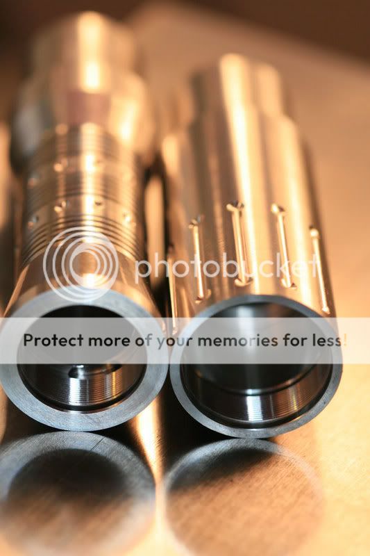
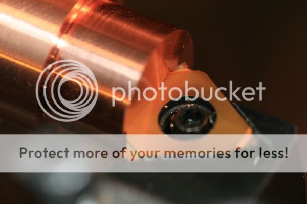
A close-up of the final bore:
That looks rougher than it felt.

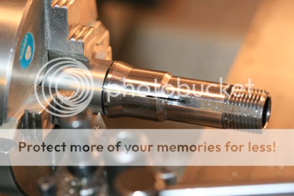
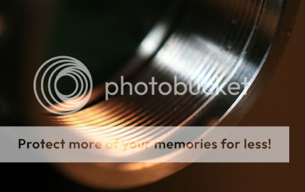
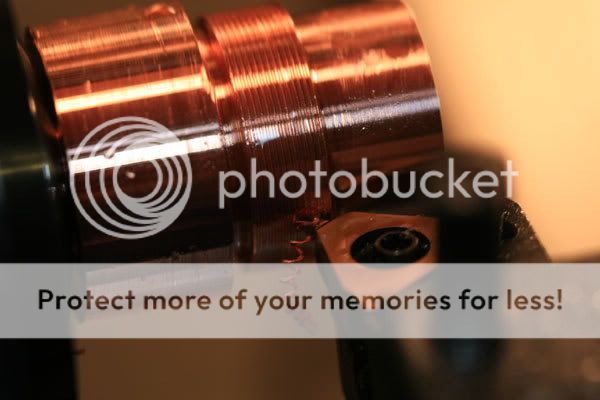
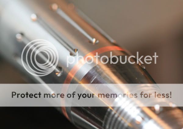
Now the head was ready for threading; first, a thread relief section was cut inside the head. This allows the threading tool a little space when it comes out of the cut, plus it gives you a chance to withdraw the tool bit in time:
The front of the threads was also relieved, using a 45-degree cut, and then the head was internally threaded:
The head needs now to be parted off and then the front of the light needs some work--boring out the light opening and putting small bezels on the front edges. Plus, I may use a grooving tool to provide a bit more room inside the head for the O-ring that the lens will push against.

 :thumbsup:
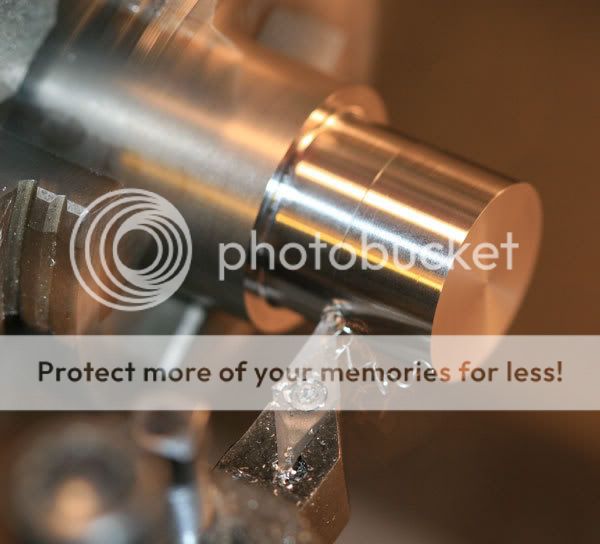


 Hi, Alex!