CMG Infinity Mod.....Lots of Pictures, updated!!

darkzero

Flashaholic* ,
Joined
Oct 7, 2003
Messages
4,459
Location
SoCal
Re: CMG Infinity Mod.....Lots of Pictures!!

That's a good question. I have some Arc AAA heads where the boards have been removed, the crimped lips just look like they were pried out.

So I attempted to do the same on the Infinity but was not successful. Every time I tried to lift a part of the crimp with a flathead screwdriver or needle nose pliers the lip just broke off on me. Since part of it had already broken off, I said the hell with it and continued on. I then ended up with the crimped lip completely broken off the head even all around.

Since this rolled lip makes the negative contact for the stock circuit, I could no longer use it unless I soldered the boards ground directly to the head or something. Since I bored out the body to fit a CR2 first, I opted for a sandwich. The head has to be bored out in order for a sandwich itself to fit. Of course the hole where the LED protrudes also must be enlarged. I also had to make a spacer for the sandwhich to make contact with the head. You might want to find someone with a lathe to do this for you. You have to bore to the point where the wall of the o-ring groove gets pretty thin. I found out the hard way. If you are off by a bit, you'll risk cutting into the groove where the o-ring would sit like I did (pictured below) which of course we do not want.

(Please keep in mind that I did all the boring freehand with a Dremel and a drill press stand)
infinity-head_bore1.jpg
infinity-head_bore2.jpg


When I finally get a lathe I will do a "clean" version of this mod but until then I will enjoy the one I have. Good luck on the mod! Please don't hesitate to ask me more, I'm always happy to help to the best of my ability. And please do not forget to share it with us when finished.
 

Justintoxicated

Flashlight Enthusiast
Joined
Dec 8, 2003
Messages
1,151
Location
El Cajon, CA
Re: CMG Infinity Mod.....Lots of Pictures!!

well i finaly got the board out, I had to get it really hot there was a TON of black epoxy type poop in there. The board made it out in one piece but the components crumbled as I pushed it though.

DZ would the stock circuit have been strong enough to drive a Red/Orange? my guess is I'll need a MM to do this properly? /ubbthreads/images/graemlins/nana.gif thanks for the help man!I will have some questions when it gets closer to polishing time /ubbthreads/images/graemlins/smile.gif

I'll see if I can get it bored at my dads work on a lathe. How long does it take, if its a 5 minute job I will likely be able to have it done
 

darkzero

Flashaholic* ,
Joined
Oct 7, 2003
Messages
4,459
Location
SoCal
Re: CMG Infinity Mod.....Lots of Pictures!!

JI, truthfully, I have no idea if the stock circuit will be capable of driving a R/O decent enough. I'm sure the Zetex circuit can be modded to drive one though. I think there is some info about it in this thread and if not specific about it the guys who posted about modifying the board should have some info for you. Otherwise, yes, a MM would be necessary if running the stock 1AA.
 

Justintoxicated

Flashlight Enthusiast
Joined
Dec 8, 2003
Messages
1,151
Location
El Cajon, CA
Re: CMG Infinity Mod.....Lots of Pictures!!

Thanks again, I think I might opt for a R/O jsut so I can continue using AA's If I went to CR2 (or It looks like a 123A might even fit) I would have to use a DownBoy Board to drive a Red/Orange which seems kinda pointless
 

spoggles

Newly Enlightened
Joined
Jan 30, 2004
Messages
46
Location
Montreal, QC.
Re: CMG Infinity Mod.....Lots of Pictures!!

anyone know wich is the positive leed on the stock ZT board?...is it the leed next to the green resistor?
 

Justintoxicated

Flashlight Enthusiast
Joined
Dec 8, 2003
Messages
1,151
Location
El Cajon, CA
Re: CMG Infinity Mod.....Lots of Pictures!!

I think it is the side that has the L1 mark on it but I'm not positive because all the components fell off my board lol but it looks like the other side conects to the outer ring which is ground. But I dunno for sure.
 

spoggles

Newly Enlightened
Joined
Jan 30, 2004
Messages
46
Location
Montreal, QC.
Re: CMG Infinity Mod.....Lots of Pictures!!

thx...the neg is the leed next to the sence resistor....trial and error hehe
 

darkzero

Flashaholic* ,
Joined
Oct 7, 2003
Messages
4,459
Location
SoCal
Re: CMG Infinity Mod.....Lots of Pictures!!

[ QUOTE ]
Xrunner said:
Darkzero, what bit did you use with the dremel to do the boring? Thanks

-Mike

[/ QUOTE ]

Mike, sorry I've seemed to have misplaced the exact bit I used (I hope I find it, it was expensive) but it was like the one pictured on the left below only it was shaped more like the one on the right (had a flat head as opposed to rounded in the picture). I've used the one on the right to do similar work but the bit type on the left works way better. The type on the left are similar to porting bits used in automotive, etc., also called burrs. The one on the right is a Dremel made bit, the burrs are not.

dremel_alumn-bits.jpg
 

milkyspit

Flashlight Enthusiast
Joined
Sep 21, 2002
Messages
4,909
Location
New Jersey
Re: CMG Infinity Mod.....Lots of Pictures!!

Darkzero, this is great work, and an amazing effort! /ubbthreads/images/graemlins/cool.gif /ubbthreads/images/graemlins/bowdown.gif /ubbthreads/images/graemlins/bowdown.gif /ubbthreads/images/graemlins/bowdown.gif /ubbthreads/images/graemlins/thumbsup.gif

I can't believe you did it all with a Dremel and some hand tools. /ubbthreads/images/graemlins/ohgeez.gif You've given all us lathe-challenged folks new hope! /ubbthreads/images/graemlins/grinser2.gif

WOW!

Any chance you could point me to as many of the attachments and other stuff you used as possible? I've got a Dremel, but want to get a burred boring head like you mentioned. Where should I look for those? What about the tap you used? What about the vise? Sorry if this is burdensome, I'm just really excited and want to start gathering up the things I'd need to attempt something similar.

Thanks!!!!! /ubbthreads/images/graemlins/popcorn.gif
 

Justintoxicated

Flashlight Enthusiast
Joined
Dec 8, 2003
Messages
1,151
Location
El Cajon, CA
Re: CMG Infinity Mod.....Lots of Pictures!!

Darkzero,

I got my head back and they bored it perfect, It fits an Ill Pill now...I need to know how large to drill the head out, should the luxeons base stick through the hole or just the dome?
 

darkzero

Flashaholic* ,
Joined
Oct 7, 2003
Messages
4,459
Location
SoCal
Re: CMG Infinity Mod.....Lots of Pictures!!

Milky, I bought the bits from e-bay if I remember correctly. I'll try and find some links and pass them along. The most important accessory that I used besides the bit was the drill press. The tap that I used was 5/8-27 but I later on found out that the correct thread is 5/8-28. The 27 worked perfect and is not hard to screw at all even with a MagAA cap. I used a vise to hold the body when threading it. No special vise is needed, just a plain ol' sturdy bench vise will do the job. I used a piece of heater hose to protect the bodu from the vise's jaws. Not a burden at all, I'm always glad to help. Please ask away. I'll try to find the links for you on the bits.

JI, at the time of the mod all I had was a low dome. My intent was to build this light as a flood light anyway. I suppose just having the dome of a HD pop out will put better use of the reflector but I'm not sure how far in as I have never tried it with a HD. I don't think the shape of the Infinity's reflector will give you good throw anyways. You're gonna have to experiment here. I bored mine out so that the entire emitter fits through the hole as you can see in the pics. The drill bit size I used was 5/16.
 

mike101

Newly Enlightened
Joined
Apr 8, 2004
Messages
108
Re: CMG Infinity Mod.....Lots of Pictures, updated

Hi guys,

I finally got my mod done last weekend successfully but not up to my expectation. This was due to I screwed up the stocked circuit board while I was doing the inductor experiment. But the Luxeon LXHL-BW01 BIN Code Q2K, which I bought from Lambda for $5.00 might be an emitter not meeting his requirement. That means I am having a second quality emitter in my mod.

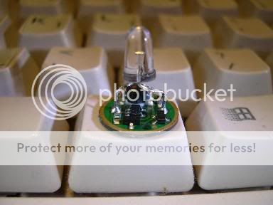
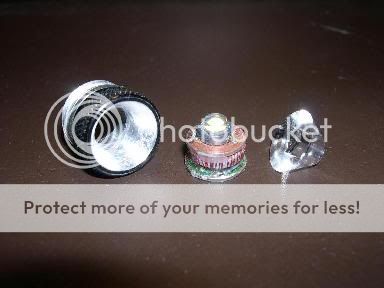
Here look at some circuit board photos first.

cmg016.jpg

CMG Infinity stock circuit board with LED

DSCN0192.jpg

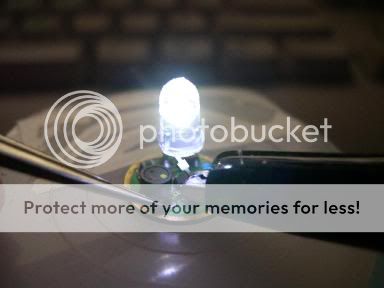
Circuit board turned on

DSCN0200.jpg

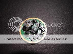
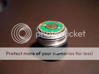
Stock circuit board w/o LED

On my post at the same thread on 4/8/04, I guessed that the inductor on the stock circuit board might be too less of power (low saturation?). Even though I got the brightness reached to the level of Ill Pill, the power consumption was very high (1.2 to 1.4 A from 2AA) and the Zetex 310 IC chip was burning hot. So I did some test with different hand-made inductors.
[Some words about the Ill Pill that I assembled. I don't know whether it is the same as the others, mine is very low efficiency, drawing about 1.4A from 2 pretty fresh AA batteries. But Lambda is having a new Ill Pill available soon.]

cmg015.jpg

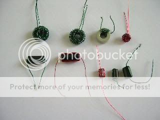
Part of tested hand winded inductors.

I wanted to control my cost low so I only used the ferrite beads and magnet wires I had on hand to do this test. The picture above showing part of my tested inductors. I winded and re-winded those beads with #30 (red) and #26 (green) with different turns for testing. The best effect would be that one most left at the bottom row. It was the same (except I used #26 wire) as that one used in Douggg's MiniMag 2AA Conversion [The actual core is a ferrite bead manufactured by JW Miller Magnetics, model number FB73-422. It's about 11mm in length and 5mm in outer diameter. We got ours from Digi-Key, part number M2308, $0.22…..Run the wire through the bead's center hole four times]. It was the brightest one because of the bead size volume and produced least heat that I almost couldn't feel at all. I measured the current draw form the battery was about 0.7A with 2 cm of sense wire. At the time of testing, I repeatedly soldered and de-soldered the hand made inductors; finally I messed up getting the SMD capacitor out from the board. It was so tiny and my soldering iron tip was so huge comparing with it, I couldn't put it back. Finally I decided to remove the diode also to make the circuit a "Maximum Battery Life Solution". At this moment I found that I could not fit this inductor with the board into the bezel. I felt embarrassed and tired, so I simply used one like used in the Ill Pill (Grey Toroid in picture, #30 wire, 40 turns). But the current so as the power both dropped. That was why I was not completely satisfied. The sense resistor was 1.8 cm including both end soldering tip. I tried a shorter one but the current either remained around 0.5A or suddenly jumped up to 1.4A and the IC was burning hot. I guessed the inductor was not good enough. I had no choice, the others were even worse.

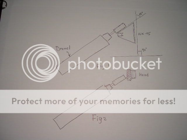
I followed what the predecessors did. I composed the emitter and circuit board in a sandwich form. The emitter was soldered onto a copper plated circuit board, so the board functioned double as a heat sink and negative contact while the flash was in turn on status. I also sanded down the NX-05 with sandpaper and final finished with toothpaste. I didn't use NX-05 at the beginning instead I did like what darkzero did by sanding the bezel shining. But the effect of light beam was not good because of lacking a hot spot. So I followed koala's trace, putting the NX-05 onto the head.

cmg004.jpg

Modded bezel, circuit board w/ emitter & sanded down NX-05

cmg005.jpg

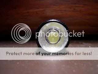
Front view of assembled head

cmg006.jpg

Another view of the head

The circuit board came out a little bit from the bezel because the thickness of the inductor. But it wouldn't drop off the bezel because the epoxy made the sandwich a little bit tight to fit.

cmg007.jpg

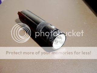
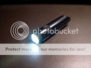
Assembled mod-Infinity

cmg008.jpg

Mod-Infinity turned on


Below are some photos of beam shot, all taken at 1/60 sec F2.7 except the last one. I positioned two flashes about one foot apart and the camera in the middle of two flashes. In these pictures the bigger circle of light spots of both flashes are the light beams spotted on the wall and the smaller circle of light spots are the reflection of the flashes. The effect of the pictures is so bad but can provide some idea of the brightness through comparison. In order to have a picture closest to my human eye perception, after a few attempts, I get the last picture. (edited: It can only show 2 pics, the others have problem to post. Since the pics effect is bad though, so I only keep the best one.)

cmg014.jpg

L. Mod-Infinity, half CR-V3 3.00V
R. Ultra G, 1 AA 1.60V
6ft from wall, 1/4 sec. F2.8
This picture shows the difference of two light is very close to my perception.

Here are some measuring of the current drawing from the batteries (All voltage are measured with the batteries unloaded):

Flash__________Battery_______Voltage___Current
Mod Infinity___1 AA Alkaline____1.595V___0.49A
_____________2 AA Alkaline____3.20V____0.51A
_____________2 AA Alkaline____2.84V____0.53A__(another sets of battery)
_____________L91 AA Lithium__1.641V___0.50A
_____________1/2 CR-V3 Li.____2.95V____0.52A
Ultra G_______1 AA Alkaline____1.595V___0.24A
_____________L91 AA Lithium__1.657V___0.25A
Ill Pill_________2 AA Alkaline____3.20V____1.65A
_____________2 AA Alkaline____2.84V____1.40A__(another sets of battery)
/ubbthreads/images/graemlins/confused.gif<font color="orange">How can I align those letters without typing lines (I want spaces)</font>

Mod Infinity run-time test, the Ultra G hosted with a fresh AA and only turn on 2 to 3 seconds 4 to 5 times an hour for comparison.

Battery__________Run-time(hr)___Human eye perception
1/2 CR-V3 Li._____0 to 1_________No brightness drop after first few minutes
________________1 to 2 1/2______Started to drop, much brighter than Ultra G
________________2 1/2 to 4 1/2___Un-attended
________________4 1/2 to 5 1/2___Dimmer than Ultra G, still bright
________________5 1/2 to 8 1/2___Dimmer, brighter than Arc AAA "moon-mode"
________________Test stopped
1 AA alkaline_____0 to 1 1/2_______No brightness drop after the first few minutes,
___________________________________brighter than Ultra G
________________1 1/2 to 2 1/2____Started brightness drop, hot spot much brighter
_______________________________than Ultra G
________________2 1/2 to 3 1/2____Overall dimmer but hot spot brighter than Ultra G
________________4______________Hot spot same as Ultra G
________________Stopped test

Run-time test with 2 AA 1.25 V NiCa rechargeable battery (5 year old, never used)

Sandwich______Run-time(min)___Human eye perception
Ill Pill__________0 to 36_______Brightness dropped from the first min all the way down
___________________________to the level of Ultra G
______________36 to 40______Brightness dropped rapidly
______________Stopped test
Mod Infinity____0 to 60_______Comparatively more stable, not watching close.
______________80___________About the level of Ill Pill at 40 min.

Run-time test with 2 AA Alkaline (fresh)
Sandwich______Run-time(min)___Human eye perception
Ill Pill__________0 to 3__________Dropped from the brightest level
______________4 to 60_________Brightness dropped every min, but very bright
______________61 to 110_______Overall and hot spot brighter than Ultra G
______________110 to 120______Same as Ultra G
______________121 to 140______Dimmer than Ultra G
______________Stopped test
Mod Infinity____Not test yet, expect to be brighter and double the time of Ill Pill.

Conclusion:
This mod proved the correctness of my first thought. That is the mod flash would be very flexible in power source. Though we sacrifice some burnt time, we still get 4+ hours of brightness which is above and up to the level of a fresh battery in an Ultra G. When you can get a CR-V3 or 3.6V AA easy and cheap, than use it to get full brightness and longer battery in-shelf life. Otherwise using an ordinary AA, with 4+ hours run time and more brightness, it still can be a light of everyday use.

Things to do:
Mod the Ultra G by replacing the inductor and sense resistor with commercial products to get higher efficiency and higher brightness. Take better photos of beam shots. Try to take pictures in every 15 min while doing run-time test.
 

Justintoxicated

Flashlight Enthusiast
Joined
Dec 8, 2003
Messages
1,151
Location
El Cajon, CA
Re: CMG Infinity Mod.....Lots of Pictures, updated

Nice Mod, I also Tried to put an I'll pill in mine...I guess tje inside I had machined out was not quite big enough and I destroyed the Ill Pill /ubbthreads/images/graemlins/frown.gif

Luckily Shiftd sent me a new chip toroid and thicker wire...So I re-constructed the Ill Pill and its Much brighter than before, I can't wait to put it against my Ill Pill With Lux III. The thicker wire, but only 27 turns is working VERY well with the Low VF LED...

Anyways I have yet to drill mine outand I'm still trying to decide wether or not I need an optic...

So how exactly did you sand it down by hand? That sounds very hard, and Won't it get scratched up quite easily? CRV3 1/2 is a direct drop in replacement right?
 

mike101

Newly Enlightened
Joined
Apr 8, 2004
Messages
108
Re: CMG Infinity Mod.....Lots of Pictures, updated

I didn't mod the Ill Pill to fit into the Infinity. The sandwich shows on the picture is the modded stock circuit board, which looks like the Ill Pill I used to compare with. The heat sink (negative) board, which I hand made is smaller than that of the Ill Pill. But it can work properly when I fit it into the Mini Maglite and it is brighter and cooler than my Ill Pill.

Answer the last question first. Yes, the CR-V3 1/2 is a direct replacement.

Sanding the NX-05 is very easy since acrylic is not a kind of strong rocky solid. I used a set in 3 sheets of sandpaper "MetalSand", bought in Home Depot for the rough sanding. Then I used 3M Wetordry 600 Ultra Fine for fine sanding, finally used toothpaste to polish. The steps as:
1. Tear off a 1-inch strip of medium sandpaper. Place and hold the strip on any flat working surface, hold the NX-05 with another hand, press it onto the strip. Start to sand the NX-05 by moving the NX-05 back and forth (not the sandpaper). After sanding with a few back and forth motions, rotate the NX-05, then repeat sanding, rotating. This would keep the surface level; of course you need to check the level frequently. Sand until it is about 1/16 inch to the desire height.
2. Repeat the 1st step with the "fine" sandpaper. Sand until about 1/32 inch to the desire height.
3. Repeat the 1st step with 600 Ultra Fine. Sand until it is a hair to the desire height.
4. Apply water on the 600 Ultra Fine and keep sanding. But starting at this moment, don't press the optic too hard otherwise it would leave some deep scratches. If you can find some 1200 or 1800 sandpaper, the result would be better.
5. When the optic reaches to the desired height, get a piece of thin, plain cotton cloth (I use my underwear, wash and wear after work is done), place and hold it on a flat, smooth and hard surface, apply some toothpaste and water on it. Place the optic and rub it on the cloth in a circle motion. Then work is done.

Since the NX-05 is easy to scratch, I am thinking to mod the optic as the one shown on this pic.
http://fuja.s22.xrea.com/review/aa_infinity_1w/in-head2.jpg
http://www.asahi-net.or.jp/~JG2T-TJM/item/inf_opti/inf_opti_m.jpg
The optic is a bit come out of the bezel. So we can always re-polish whenever it gets scratches. But I don't have a lathe, I'm still thinking a way to make the edge look great.

BTW, I sanded down my Maglite reflector in the same steps. Just don't need the 3M 600. One little experience is to cover the reflecting face with some Scotch tape before the sanding.

Compare with the optic, modding the bezel is a harder work. What I had done is:
First drill to enlarge the hole with a 3/8 inch drill. Then hold the Dremel in level on a working table surface in the angle "a" as shown on Fig 1 (for safety, mount it with some tool).
DSCN0334.jpg
I
Hold the bezel in 90 degree, slowly move the hand, leading the bezel, the inner side of the hole towards the grinding head. Only let the part in "6 o'clock" of the bezel to touch the grinding head and grind. Keep the bezel at that position and level, rotate the bezel like turning a number lock. Check for the grinding surface, angle, depth, etc. frequently. When you feel almost done, put the emitter and the optic in place to check if the optic reach the depth of focus. If it is in focus, you can see the whole optic reflecting the yellowish color. At this moment you need to grind a hairy depth more because of when applying epoxy to fix the optic, the epoxy would increase the height. This is my experience, my mod now is a little bit off focus. (After thought: May be instead of grind down a little bit more, we can sand the grinded surface as what darkzero did. The shining surface would look much better and help the beam.)

Hope this can help who want to mod something like this.
 

Justintoxicated

Flashlight Enthusiast
Joined
Dec 8, 2003
Messages
1,151
Location
El Cajon, CA
Re: CMG Infinity Mod.....Lots of Pictures, updated

aww damn I destroyed the stock circuit...I think I will replace with MM+..Your info on the grinding will help, I'm not sure if I will go with an optic or not I guess I can polish the reflector and see if it is good enough.
 

shiftd

Flashlight Enthusiast
Joined
Nov 17, 2002
Messages
2,261
Location
CA
Re: CMG Infinity Mod.....Lots of Pictures, updated

Justin, i think on your mod, using MM lite would be a better approach. It is more efficient on single AA, less heat generated on one CRV3 and more run time overall, which you would want for an edc anyway.
 

mike101

Newly Enlightened
Joined
Apr 8, 2004
Messages
108
Re: CMG Infinity Mod.....Lots of Pictures, updated

I tried to take some pic with better effect. Finally I got these two I was quite satisfied. All pics were taken at F2.8, 1/4 sec, flashes and camera were 6 feet from garage door, all batteries were fresh.

DSCN0349.jpg

Left: Mod Infinity, NX-05, 1 Energizer AA
Right: Ultra G, 1 Energizer AA

DSCN0348.jpg

Left: Mod Infinity, NX-05, 1/2 Panasonic CR-V3
Right: Ill Pill in Mini Maglite, sanded down reflector, 2 Energizer AA

From the first pic, we can see that both flashes are almost the same. In actual, I feel the M.I. is slight brighter than the U.G. especially at the hot spot. Though it is an improvement for a Infinity leveled up to an Ultra G. But according to the predecessors, the light should be brighter even just adding a sense wire. As koala stated in his post,

[ QUOTE ]
Obeck, the infinity ultra drives the nichia 5mm LED at 66ma 1.5v stock. That's way overdriving.

It pumps out 260ma at 3v stock.

-After- the sense resistor mod, my infinity pill pumps out 180ma at 1.5v. Which is not alkaline battery friendly, refuse to start when the battery drops to 1.25v. NiCd and NiMh are fine.

[/ QUOTE ]
180ma at 1.5v, does it mean that my mod should be about 3 times as bright as the Ultra G?/ubbthreads/images/graemlins/confused.gif
I did measure the current flew through the emitter while the orginal inductor was still on the circuit. I could never reach 180ma with a single AA. But my measurement might be inaccurate since I used some pairs of crocodile clips for connection. This way increased a lot of impedence and affected the result. The other thing I don't know is whether the inductor in Infinity Ultra (koala's mod) is the same as the one in Infinity (my mod). I did not measure the current after I replaced with my hand made inductor so I had no idea the current now.
I recalled that when the original inductor was still on board, I shortened the sense wire trying to get higher current. I could only get higher Iin, the Iout remained on a certain level. So the excess current burnt the Zetex 310 so hot that I couldn't touch it.
If koala read this post, can you give me some info about the brightness of you Infinity Ultra mod compare to the original one?
One more thing is that I used an emitter that probably did not meet the standard.
 

darkzero

Flashaholic* ,
Joined
Oct 7, 2003
Messages
4,459
Location
SoCal
Re: CMG Infinity Mod.....Lots of Pictures!!

[ QUOTE ]
darkzero said:
Milky, I bought the bits from e-bay if I remember correctly. I'll try and find some links and pass them along.

[/ QUOTE ]

Milky, here's a couple links and alot better deals than what I got:
Link, link.

Just search for carbide burrs. They're mainly used for alumn a common in porting. The double cut ones are better. I look on ebay cause these type of bits are pretty pricey.
 

darkzero

Flashaholic* ,
Joined
Oct 7, 2003
Messages
4,459
Location
SoCal
Re: CMG Infinity Mod.....Lots of Pictures!!

Mike101, very, very nice! It looks like quite a bit of hard work but I'm sure was well worth it. Blows my mod out of the water. So....when ya gonna make me one? /ubbthreads/images/graemlins/wink.gif
 

Latest posts

Top