Disclaimer: These kits are the ones I have available for sale in my Joule Circuit sales thread, but you can certainly use this tutorial to came up with your own kit/project.
Tutorial for AA Kit (3mm and 5mm)
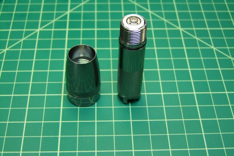
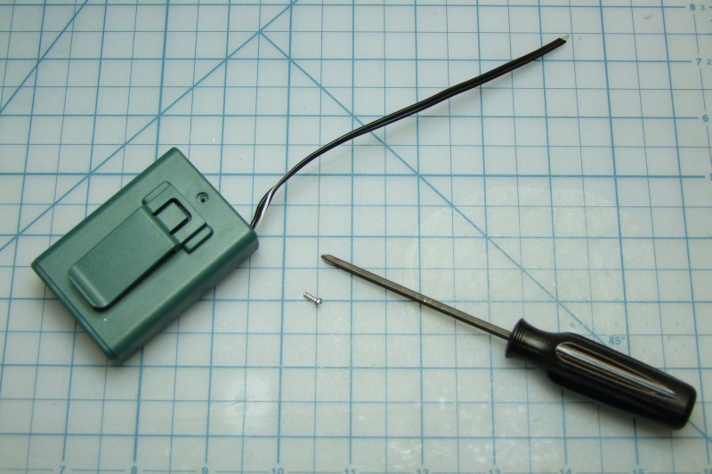
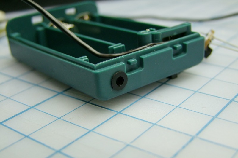
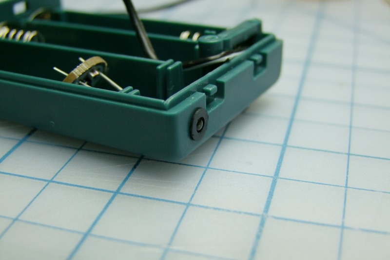
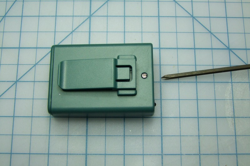
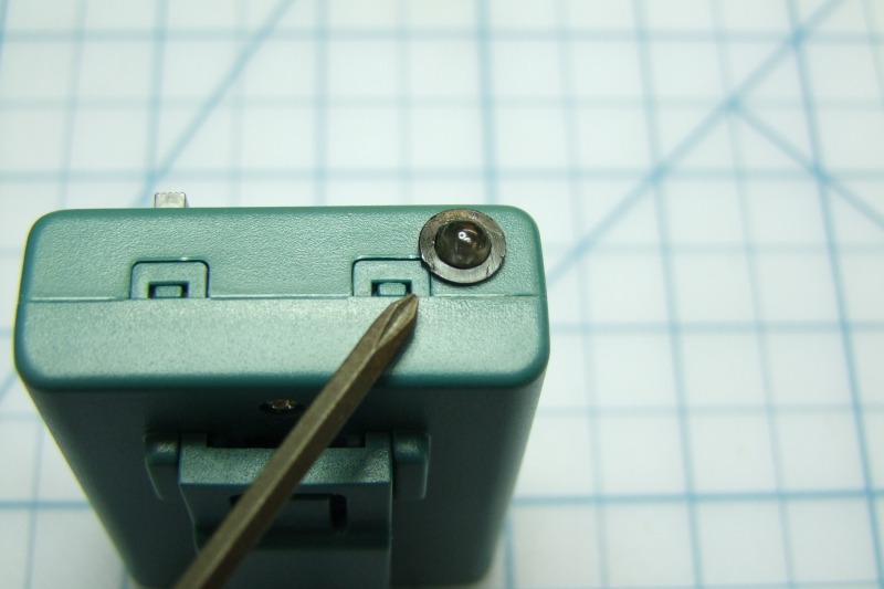
Start by opening the case by removing the small crew:
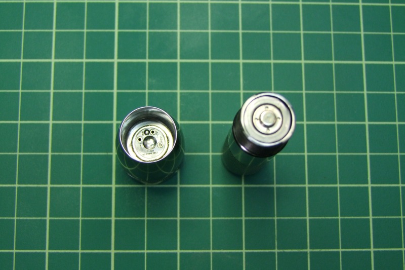
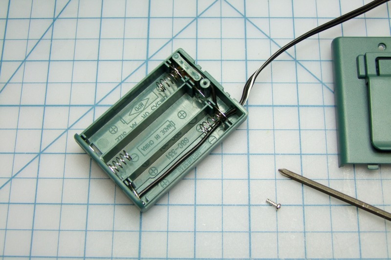
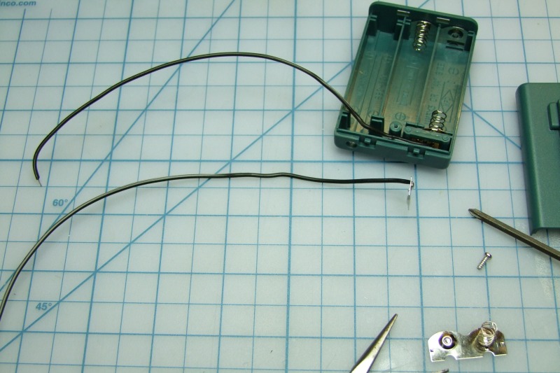
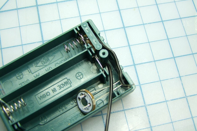
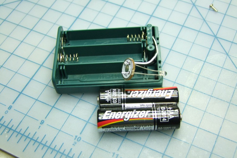
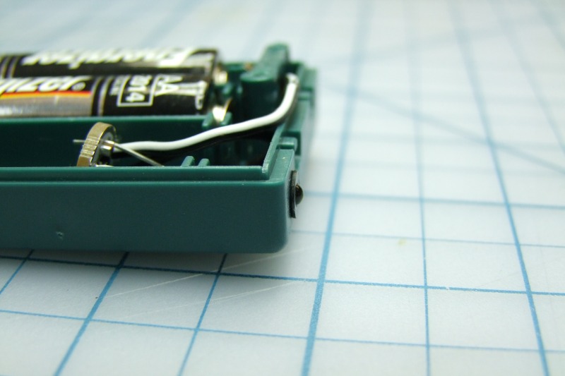
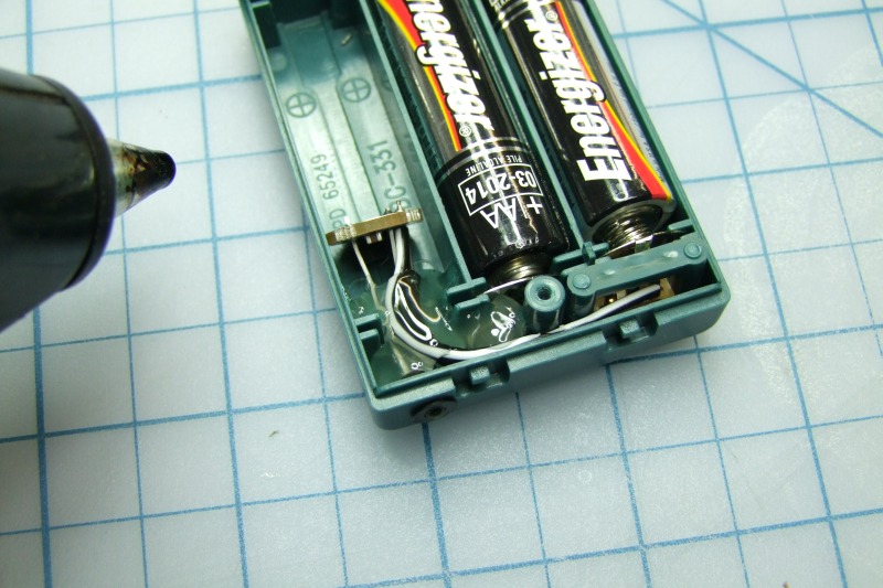
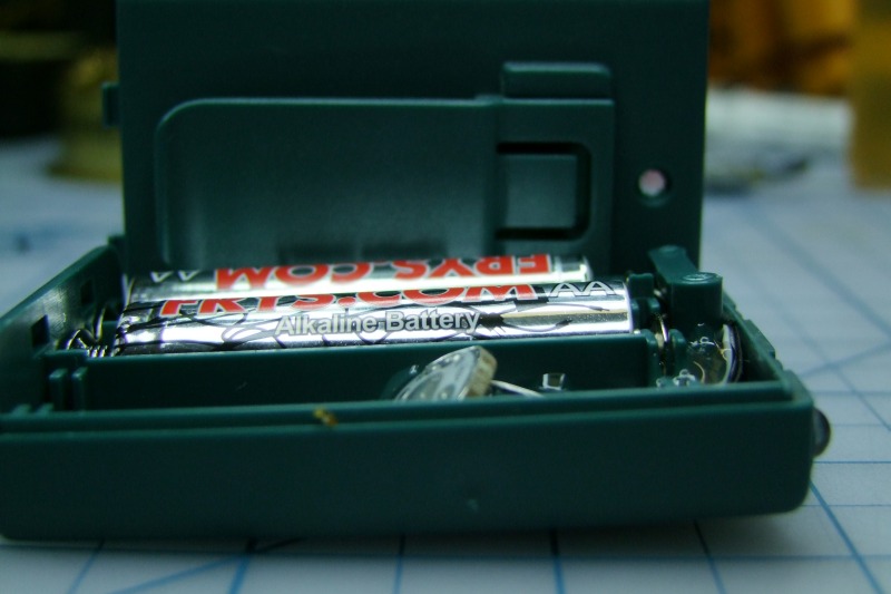
Here is the open case:
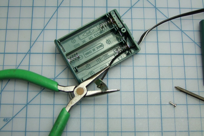
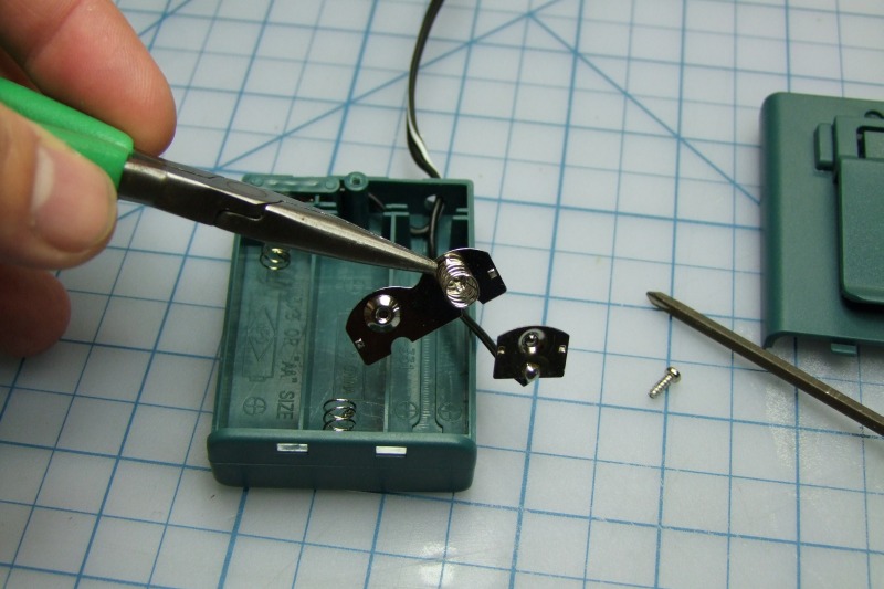
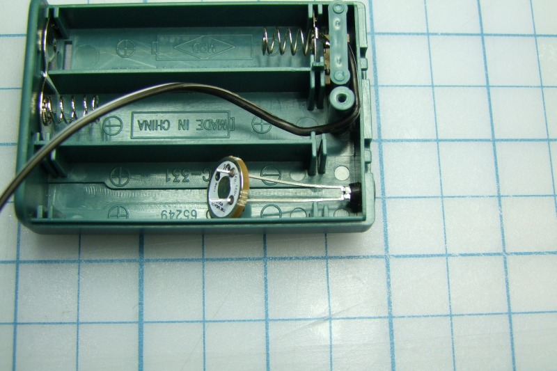
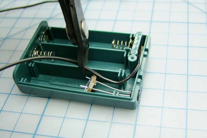
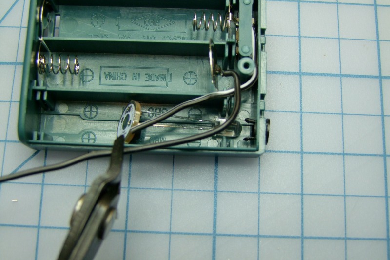
Start by removing the positive wire (the black cable without the white stripe):
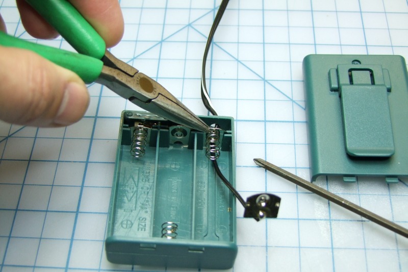
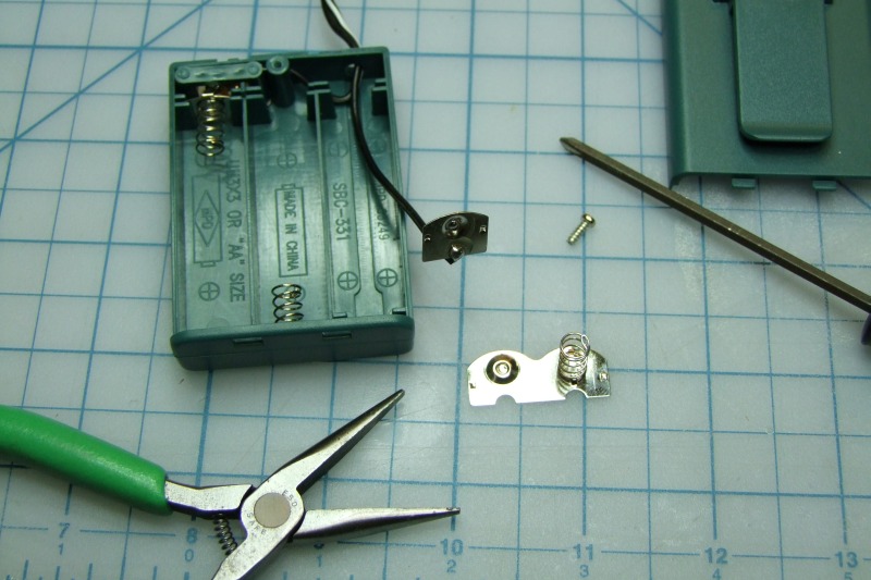
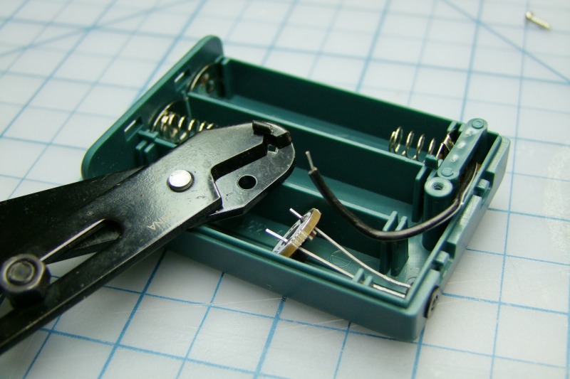
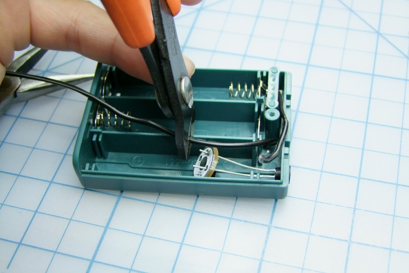
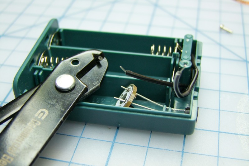
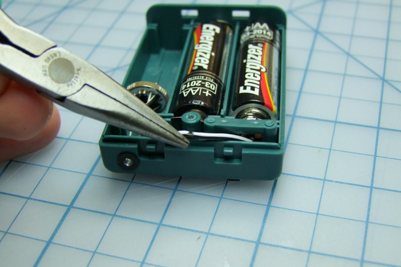
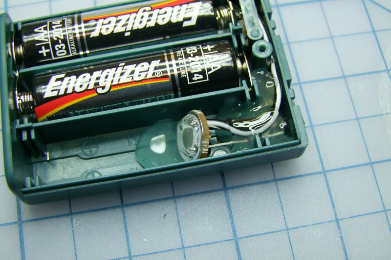
Then remove the dual battery connector and discard it - we are not going to use it all:
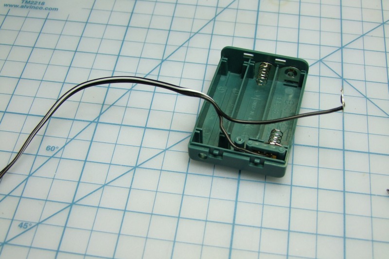
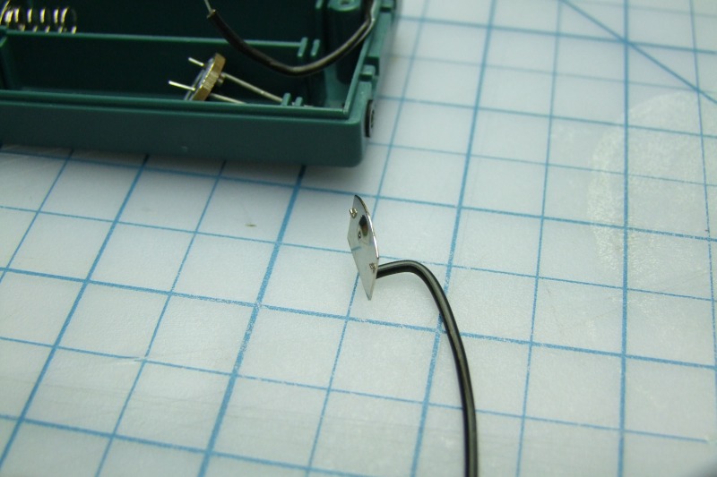
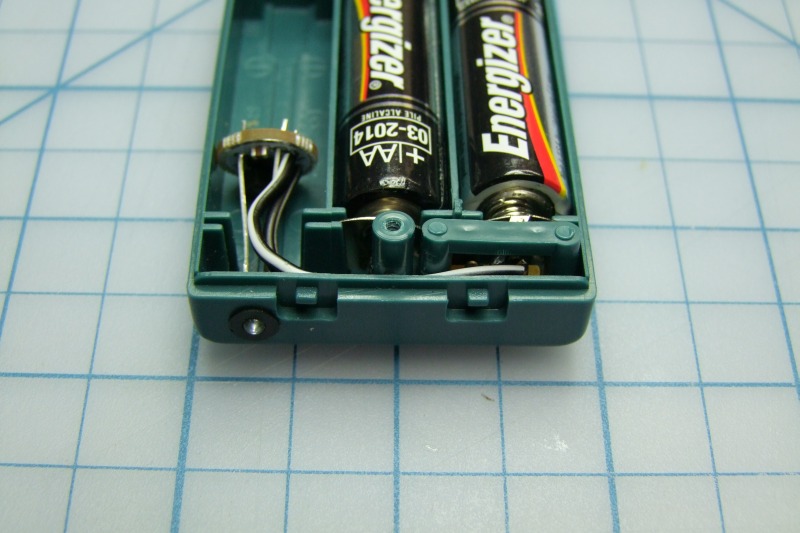
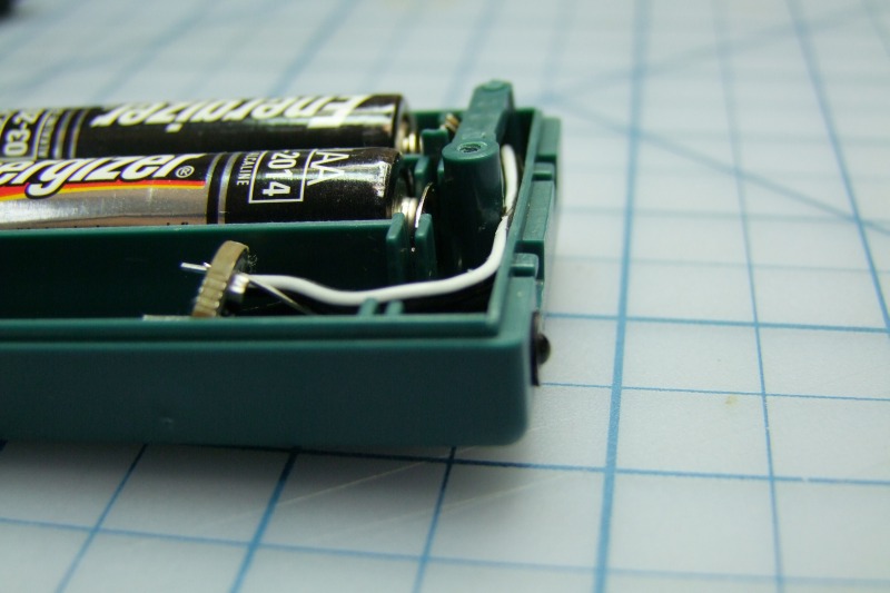
We then push the cable all the way through the small hole:
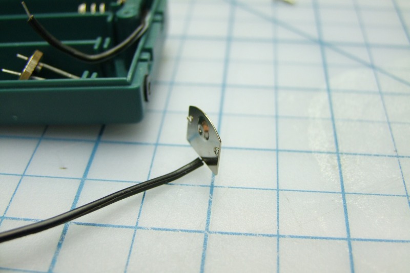
Then separate the two conductors (one is solid black - which is the positive wire, and one black with a white stripe which is the negative wire):
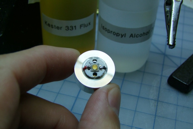
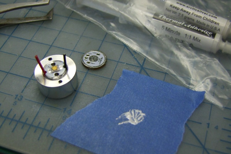
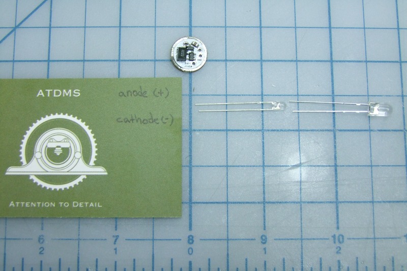
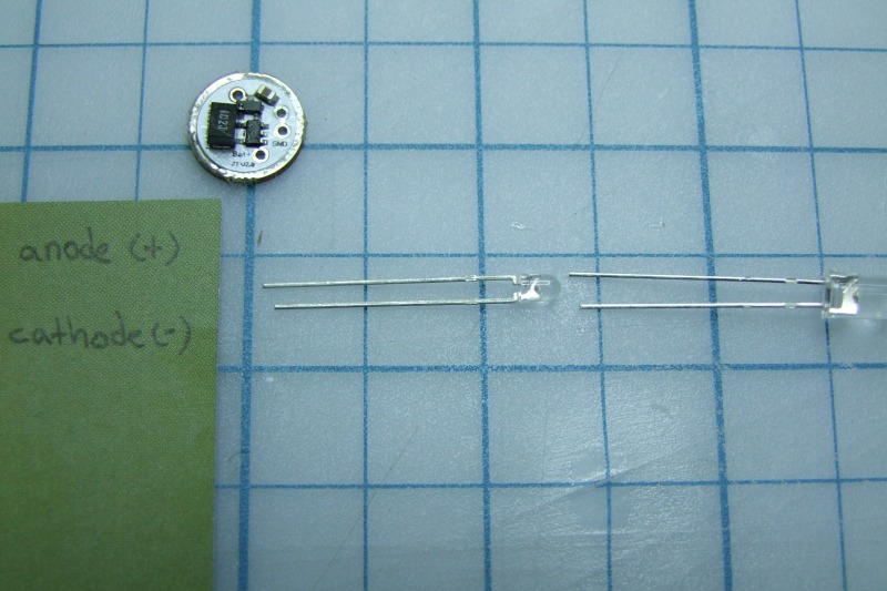
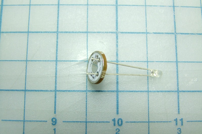
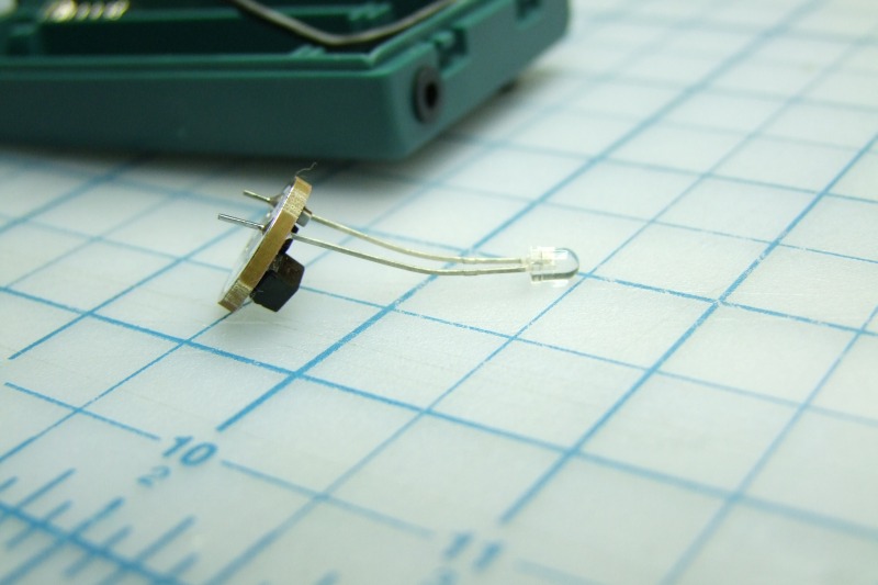
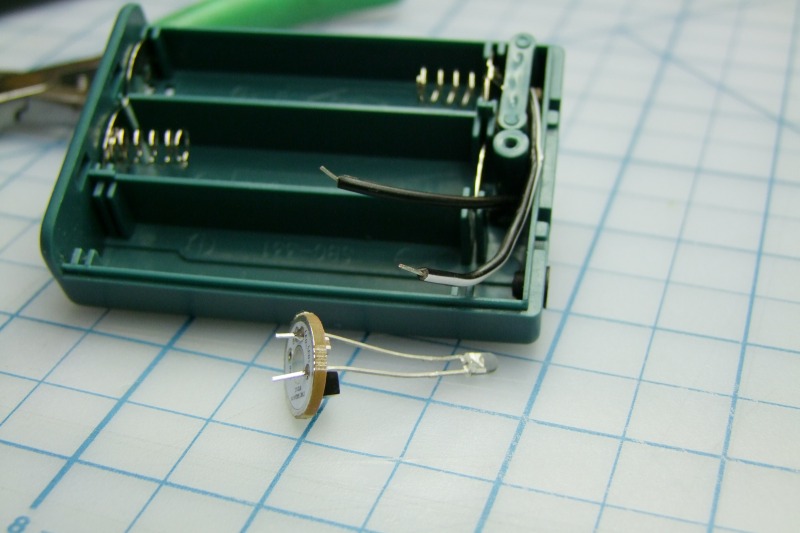
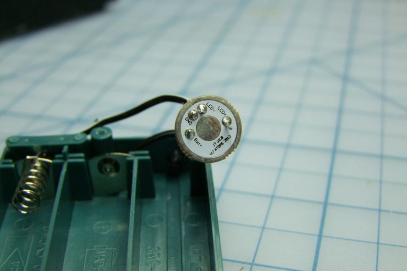
Now note the anode (+ leg on the LED) and the cathode (- leg on the LED). The anode is the slightly longer leg, which in this photo is above/on top:
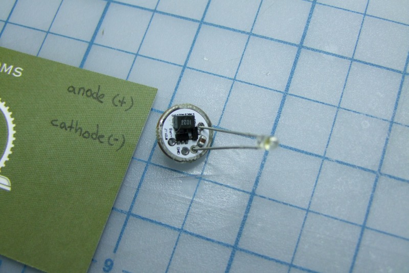
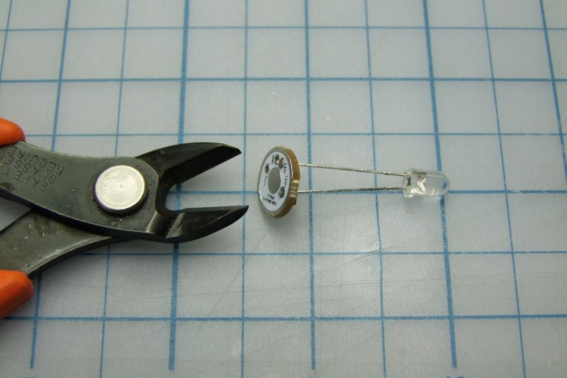
Then align the LED to the Battery Vampire (Joule Thief) board by slightly spreading the legs. In this particular photo, the anode (slightly longer leg) goes towards the inductor - this is the LED+ on the board, and the cathode goes into one of the two small holes side-by-side - that is the LED-:
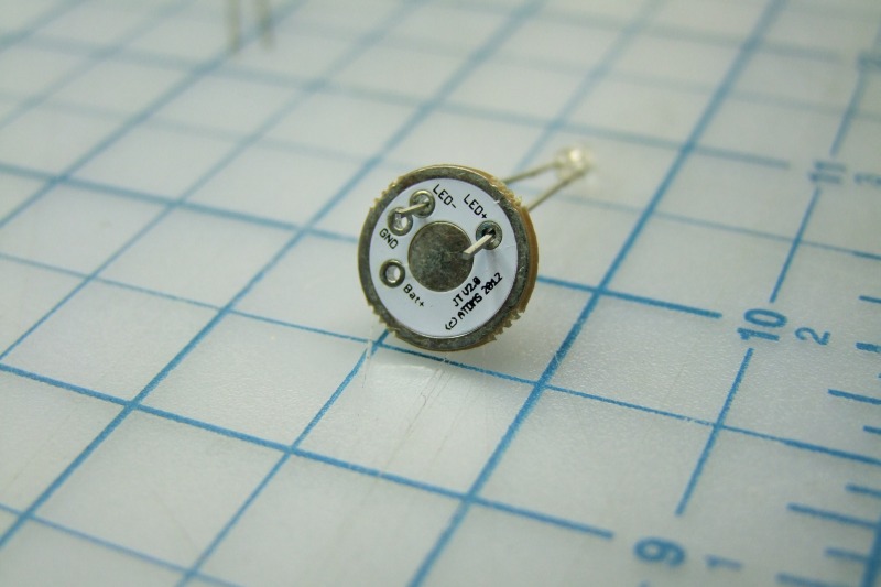
Here in this photo, the board and LED are backwards in order to solder them, but you can clearly see the longer leg (anode) inserted in the LED+ hole:
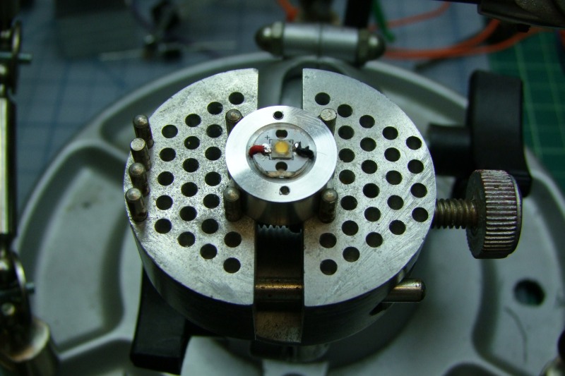
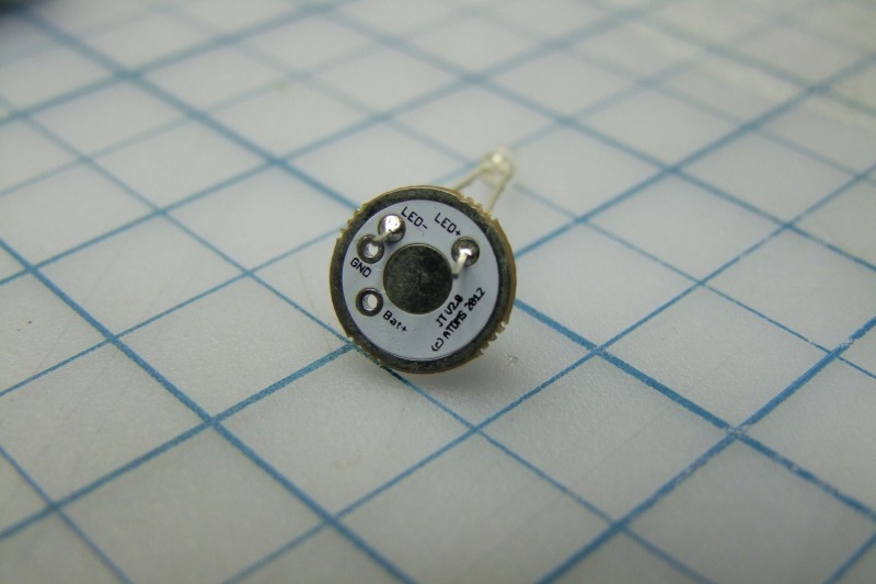
Then solder the two legs in place:
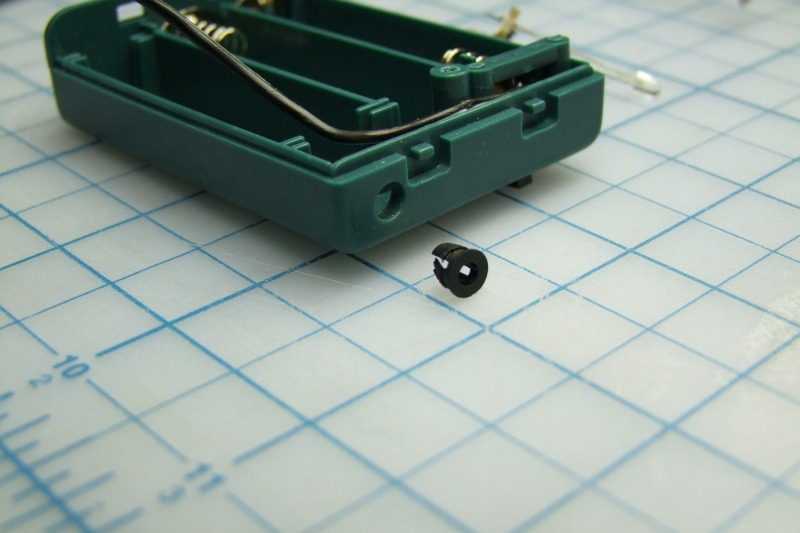
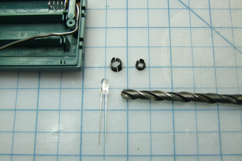
This is the 3mm LED holder - it fits on the stock wire opening (a little tight with the LED in place, but it does fit):
In order the align the board and LED with the LED holder, slightly bend the LED legs as shown here:
Here is a test fit to show you how it would look like. Note that the anode (LED+) sits down, closer to the edge of the case:
Measure the ground wire (black wire with white stripe) and cut it:
Then expose the wire to make ready for soldering:
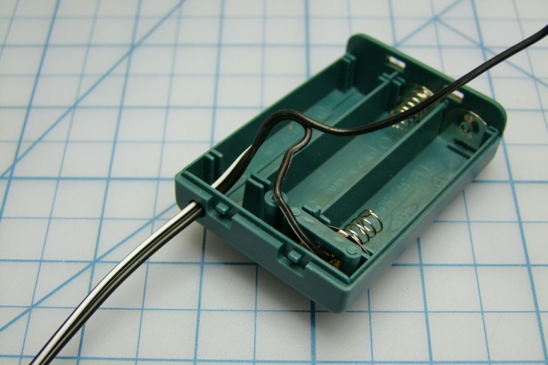
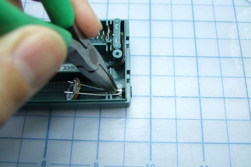
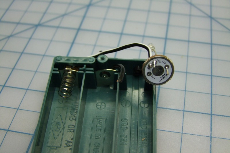
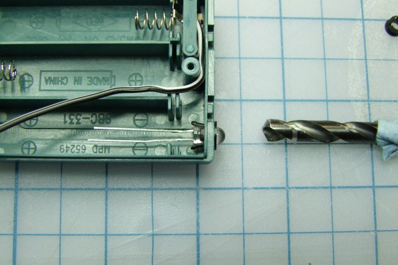
Rake the positive wire and carefully bend the wire backwards and then on a 90 degree turn as shown:
Insert positive wire into case as shown:
Measure and cut the positive wire as shown:
Then expose the wire to make ready for soldering:
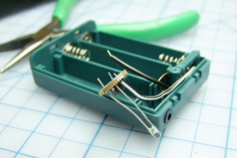
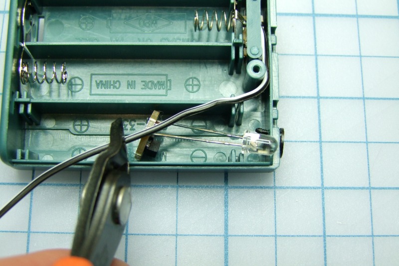
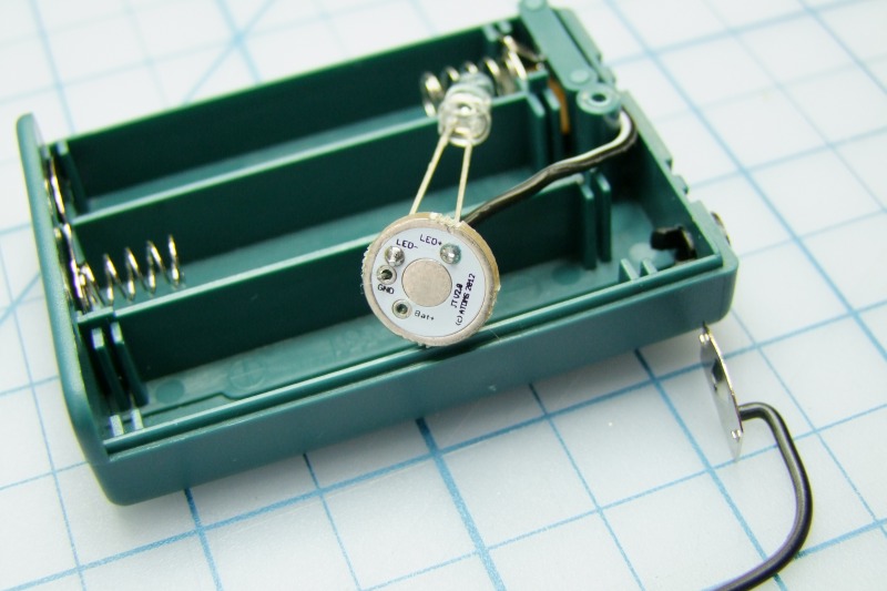
This is how things should look like prior to soldering. It is much easier to solder with the LED outside of the box:
Then expose the wire to make ready for soldering:
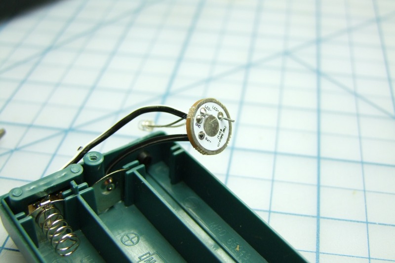
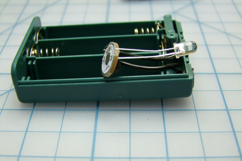
Align the negative wire (the one with the white stripe) with the hole in the board marked GND and solder it in place:
Now align the positive wire with the hole in the board labeled Bat+, and solder it in place:
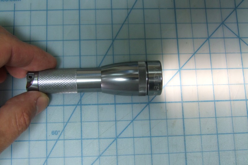
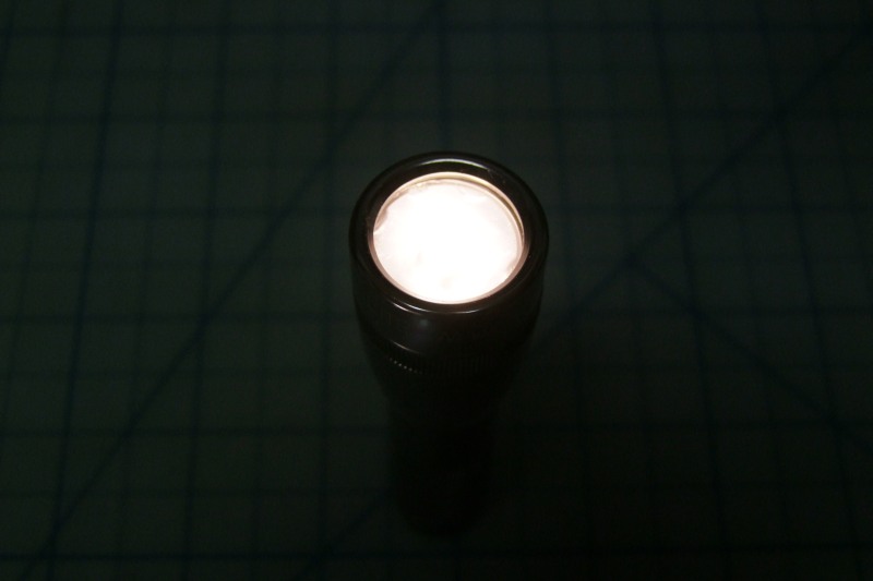
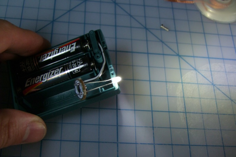
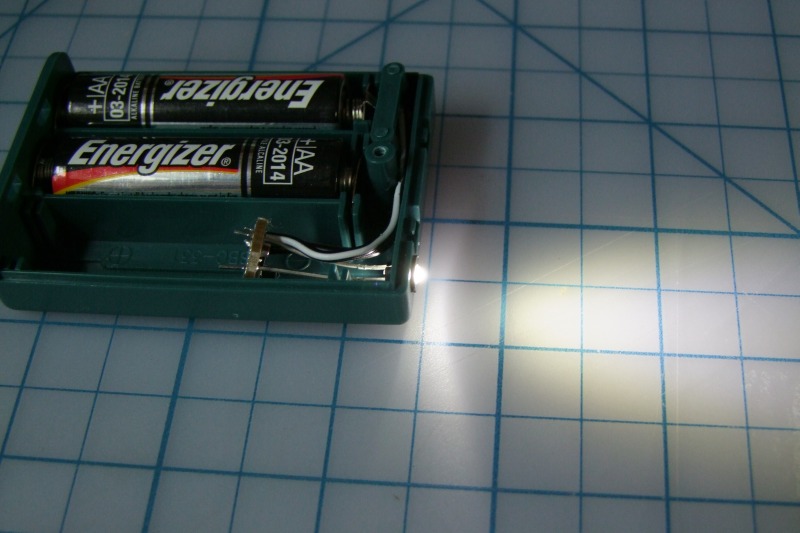
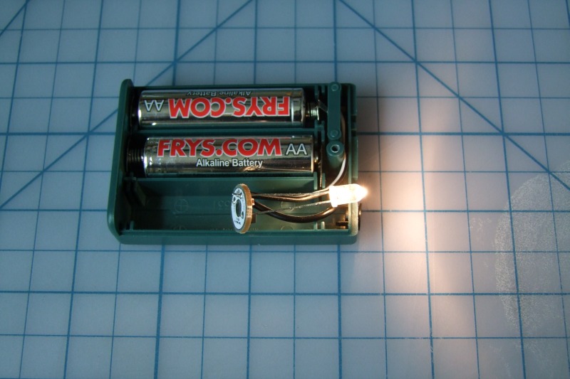
Before we go any further, we need to test it - it should be fully functional right now:
I test each driver before shipping, so if it does not work, and you have not kill the driver with static electricity (you should be grounded while working on this or any other circuit boards), then it must be a wiring problem, cold solder joint, etc.. Check your steps and re-wire/touch-up solder points as appropriate.
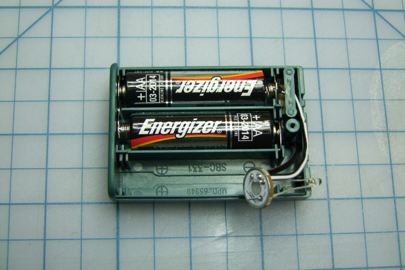
Now, in order to close the cover, we need to tuck in the negative wire back in its original position:
Another quick test:
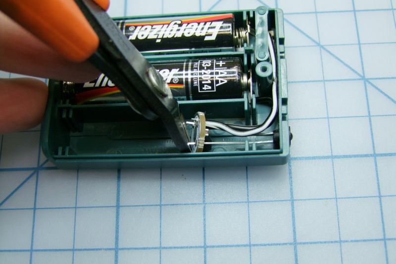
You should have cut off the extra wire/legs sticking out earlier, but if not, do it now (make sure the small pieces don't fall inside the case and short something!):
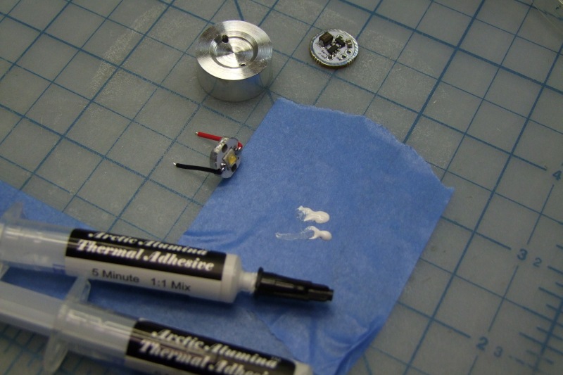
Here I have two of them ready for the hot glue:
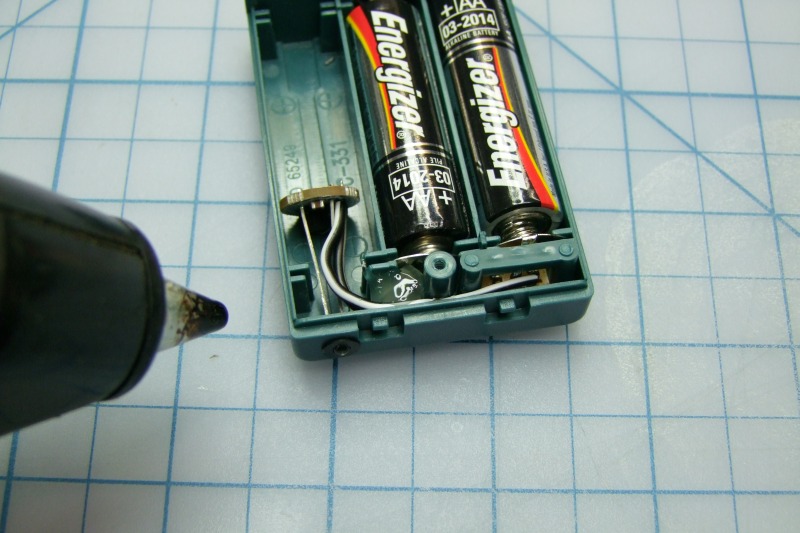
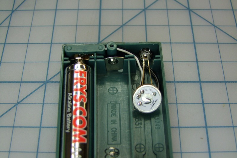
We need to make sure that positive metal contact and wire don't move and don't come off its alignment, so we start there:
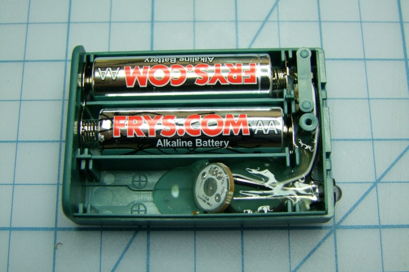
Then we add hot glue over the LED legs and wires to keep everything from moving and prevent shorts from external debris:
Finally apply hot glue to the back/bottom side of the driver to cover the electrical connections and prevent short from external debris:
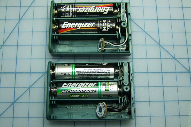
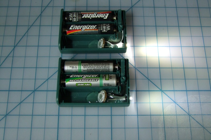
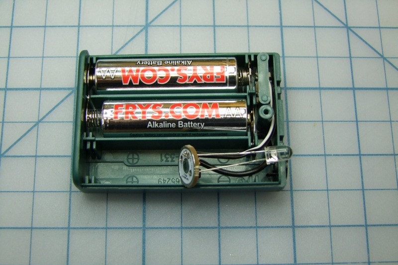
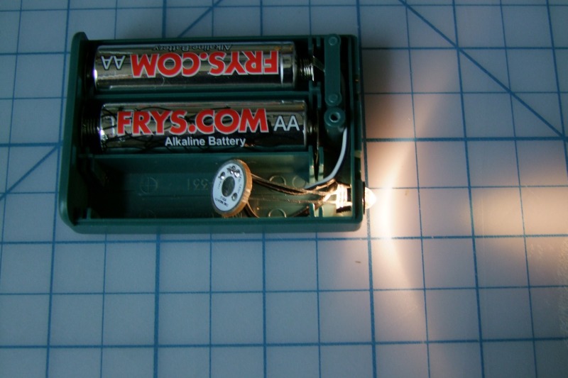
Another quick test (I know, it sounds paranoid, but that is how I do all projects) - the rechargeables are not fully charged and the Energizer cells are new, so there is a brightness difference:
Put the screw back in, and you are done!:
**********************************************************************
The 5mm version needs more work, so here are a few more pictures/steps for the 5mm version
Note the 5mm LED and holder are of course larger. The hole in the case which worked well for the 3mm will not do - it will have to be enlarged by using a 1/4" diameter drill bit:
As before, align the anode/cathode, and solder in place. It is best to trim the excess here:
As before, measure the negative wire (black with white stripe) and cut it, then same for the positive wire (solid black):
As before, align wires with the matching holes in the board and solder in place:
Time for a quick test. Yes, as expected, the 5mm LED is brighter than the 3mm LED:
Tuck the negative wire in the case, and test again:
As before make sure before applying the hot glue that the positive battery contact is aligned and centered in the case:
And use hot glue as before to keep everything in place and safe for external debris:
Note that the circuit board should sit slightly below than the top of the AA cells, so that the cover can be put back in:
When putting the case back, note that there is a little bit of interference from the 5mm holder and the edge of the case at this point (you can trip it or leave it "as is"):
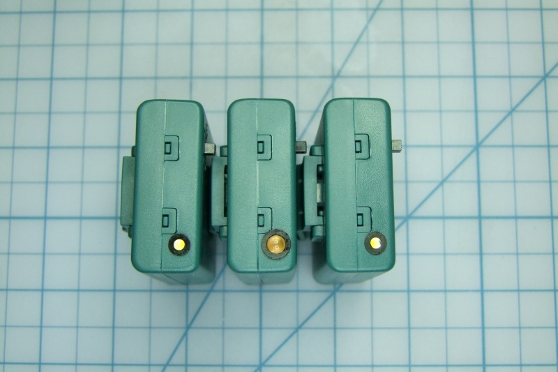
Here are 3x completed units: 3mm, 5mm, and 3mm:
Will

")