bro,
I think I know what you mean...No, you only need one protection circuit for the pack, which will be made up of any number of batteries connected in parallel and then in series to make the voltage you want.
You do need to source the correct PCB for the number of cells you want to build.
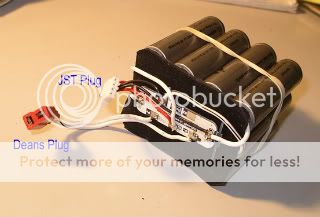
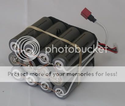
Probably easier to have a look at these pictures. This is a 10Ah 11.1V (3 cell) pack made up of 12*18650 batteries. Each cell is a row of 4 batteries connected in parallel, and then these rows or 'cells' are connected in series with the other rows to make up the 3 cells.
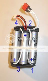
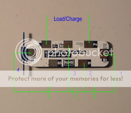
Compare the circuit diagram with the numbered leads in the photo. You will see how the four leads come up to the PCB.
This PCB can be used for either a 3 cell or 4 cell pack. In a 3-cell the contact marked 'B3' is ignored.
The JST plug is for balance charging and has its 4 leads connected to the batteries using the solder pads of the PCB. If you want to balance charge then check the charger as it will have the polarity marked on the plug port. You then plug in the JST to see what plug lead needs to go to what cell join.
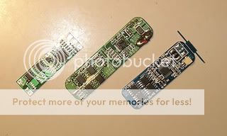
Some examples of 3-cell PCBs above. The one on the left is 3 Amp limited while the two on the right are 5Amp.
Quick question regarding this diagram and using 4s pcb's for 3s packs.
I bought a tenergy ryd-03/4s, along with 4x tenergy 3568100 3.7v 2400mah lipo cells. The plan was a 4s pack, but one of the tabs broke of a cell, and i tried to solder a lead on it, until i became uncomfortable getting that close to the actual pack. Sanded/tinned/ tried everything, but just wasn't going to take a lead.
So a google search turned up this thread, and i wired up my pack in the same config you have, but with the above fore-mentioned pcb/cells. But, even though measured through the unprotected cell i get the right voltage, and all cell contacts to the pcb read the right voltage, as well as all being ~3.8 +/- 100mv (one is 3.9v), i dont get any power on the charge/discharge leads. The cells were charged last night, one by itself on a tenergy b6s+, the other two as a 2s pack on the same charger. The pack was protected w/ balance leads, and the single i just alligator clipped to the +/- charger leads. The 2s pack had only been fully discharge/charged once, and pretty much the cells are within range of similarity to be called identical in health/charge/usage.
I'd hook it up to the charger, but i'm a bit heasitent to do so, but i don't think theres any risk, just want a second opinion as to if its safe to do so before hand. I would assume the charger would detect the fault before anything got
out of hand, or it charged a miswired pack.
Heres a few pics of the pack, the pcb with a heat-sink on it is a sepic, which i will tune to 5v, and has a female usb lead for charging usb devices. The switch is to switch between that (sepic regulator), and the charge/discharge barrel connector. Discharge just meaning i could plug a barrel connector to the same port i charge from, while the switch is in charging position, and bypass the sepic regulator. Just don't want the sepic exposed to the charger when the pack is charging.
Bad pcb? This model pcb doesnt work in a 3s config? 3s with a 4s pcb won't work with poly lithium cells?
Any comments/suggestions are most welcome :naughty:

")

 .
.