Low voltage LED options for the FM C-cell “C” bodies w/ SF KT-2 TH **More Beamshots**

MrGman

Flashlight Enthusiast
Joined
Feb 6, 2007
Messages
1,777
MrGman, that is good info, and it shows that the voltage regulated boost M30 is a very flexable driver, the way that Gene has set it up.

Bill


Yes it is so you can get a good peak output if you can run it off 4.5V and you will know that the batteries are fading as the output slowly goes down. No sudden drop without warning. It was very interesting to get these numbers. The M30 can be made to be much brighter than the M60 if one uses care not to overdrive it.

That is not to say the M60 isn't a good module, its a very good module and very well regulated with the voltage reduction buck type driver.

I have to do this some time with the MC-E units. :D
 

Justin Case

Flashlight Enthusiast
Joined
Mar 19, 2008
Messages
3,797
The tower I built for Kestrel had a much higher lux reading for the hot spot using a 12ZM TH on a 3P host vs my M30 driven by one 16340 in a 3P with a current version 6P bezel with Pyrex window. I don't recall the midpoint spill readings for the two modules, however. But my observations for my SOB1000/P4 and SOB1000/MC-E towers has shown a great combination of hot spot intensity and bright spill using both the 12ZM TH and a KT4 TH.
 
Last edited:

Justin Case

Flashlight Enthusiast
Joined
Mar 19, 2008
Messages
3,797
The BBNG uses the TPS61030 boost IC. Here is a description from the datasheet for the IC's startup procedure:

"When the device enables the internal start-up cycle starts with the first step, the precharge phase. During precharge, the rectifying switch is turned on until the output capacitor is charged to a value close to the input voltage. The rectifying switch current is limited in that phase. This also limits the output current under short-circuit conditions at the output. After charging the output capacitor to the input voltage the device starts switching. Until the output voltage is reached, the boost switch current limit is set to 40% of its nominal value to avoid high peakcurrents at the battery during startup. When the output voltage is reached, the regulator takes control and the switch current limit is set back to 100%."

The IC spec also states 4A typical switch current limit. The startup current limit, as stated above, is 40% of the switch current limit, or 1.6A.

In my Vf measures in a previous post, I measured 3.37V for an SSC P4 driven by an SOB1000 driver (for both 2xLi-ion and 4x123A battery sources), and 3.27V for the SSC P4 driven by a BBNG1000 driver (2xAA Eneloop battery source).

My assumption from before was that 3.37V is probably the Vf at 1000mA drive current (If) for that particular LED, since 2xLi-ion and 4x123A have input voltages far above what the SOB1000 needs to run in regulation.

The question is if the P4 being driven by the BBNG is running at 1000mA drive current or something lower. The lower Vf suggests that the BBNG isn't running full-speed, although Vf for LEDs certainly has enough variation that 3.27V could be the Vf at 1000mA drive current.

So, now let's factor in the specs for the TPS61030 IC being used in the BBNG.

If we assume BBNG1000 efficiency of either 80% or 90%, Vf of either 3.27V or 3.37V at an If of 1000mA, and Vbatt of 2.4V:

(0.8 or 0.9) * 2.4V * Ibatt = (3.27V or 3.37V) * 1A

We get

Ibatt (80% efficiency, 3.27V Vf) = 1.7A
Ibatt (90% efficiency, 3.27V Vf) = 1.5A
Ibatt (80% efficiency, 3.37V Vf) = 1.76A
Ibatt (90% efficiency, 3.37V Vf) = 1.56A

If Vbatt is closer to 2.5V, then we could get

Ibatt (80% efficiency, 3.27V Vf) = 1.6A
Ibatt (90% efficiency, 3.27V Vf) = 1.45A
Ibatt (80% efficiency, 3.37V Vf) = 1.69A
Ibatt (90% efficiency, 3.37V Vf) = 1.5A

So, depending on BBNG efficiency and Vbatt, the IC may or may not be running in regulation. Another variable is that the switch current limit is also spec'ed at a minimum of 3.6A and a maximum of 4.5A. Thus, the startup current limit can range from 1.44A to 1.8A, with a typical value of 1.6A.

I guess the best one can say right now is that trying to run in regulation for a BBNG1000 driving a Seoul P4 U2xxH-bin with 2xNiMH is cutting it close.

But even if the BBNG isn't running in regulation, IIRC Wayne at The Sandwich Shoppe estimated that the safe mode If is around 750mA, which still should give at least 180 emitter lumens.

At least for me, there is the remaining question as to why the measured current at the tail doesn't read higher than the 1.2A observed. One would think that the current at the tail would be more like 1.4A-1.6A, running or not running in regulation. That's one reason why I wonder about DMM sense resistance and DMM probe resistance effects.

Edited:

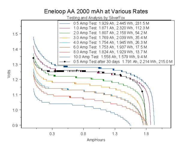
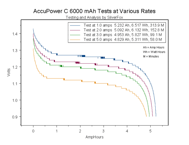
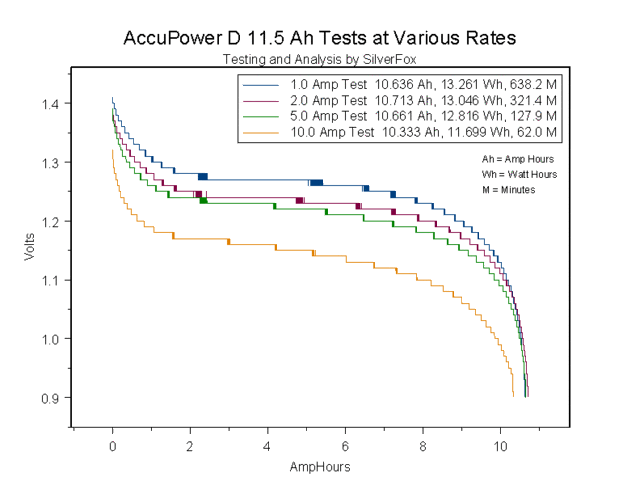
This NiMH shoothout thread by Silverfox shows the performance of AA Eneloops and Accupower C and D cells. Here are the three graphs reproduced below:

EneloopAA2000atVariousRates.gif

AccuPowerC6000atVariousRates.gif

AccuPowerD11500atVariousRates.gif

For the C and D cells, fully charged NiMH cells can hold above 1.3V even under 2A loads for around 15 min to 1 hour. The Eneloops, in comparison, look like they can hold above 1.3V for about 2 min. Still, this should be enough to start the BBNG in regulation. Let's see. Now, we assume that Vbatt=2.6V. This gives

Ibatt (80% efficiency, 3.27V Vf) = 1.57A
Ibatt (90% efficiency, 3.27V Vf) = 1.4A
Ibatt (80% efficiency, 3.37V Vf) = 1.62A
Ibatt (90% efficiency, 3.37V Vf) = 1.44A

This looks better, though still close for the usual conditions of lower driver efficiency and-or higher Vf.

What I plan to do is charge up my Eneloops and test them hot off the charger in my 2C Mag mod to see what Vf I might measure. Maybe this is also the motivation to buy some C and D NiMH cells and see what difference they might make.

Edited:

I charged my Eneloops in the Eneloop charger, pulled the cells, and then let the cells sit overnight. I then popped them into my Maha C401FS charger and topped off the cells. When the green light came on, I pulled the cells and they measured 1.486V and 1.492V (2.978V total, resting). Put the cells into the 2C Mag P4/BBNG1000mod and I measured Vf=3.28V.

I recharged the Eneloops and measured 1.499V and 1.503V, resting voltage. Current draw at the tail was 1.19A. I then left the light on for 10 min continuous. Upon removal from the 2C Mag, the cells measured 1.319V and 1.320V. I re-installed the Eneloops, didn't let the light cool down any additional amount, and measured 1.17A at the tail and Vf~ 3.24V. I measured 18,900 lux at 1 meter for the hot spot and 70 lux for the midpoint of the spill (same as with fresh Eneloops).

I also measured another P4/SOB1000 AW Turbo Tower running in a 12ZM. For both 4xSF123A (12.28V total, resting) and 2xAW17670 (8.40V total, resting), I measured Vf=3.30V.
 
Last edited:

Justin Case

Flashlight Enthusiast
Joined
Mar 19, 2008
Messages
3,797
Kestrel,

Please measure current draw at the tail using your 2C FM body and your 3C FM body, with 2xC NiMH and 3xC NiMH respectively. A good indicator of running in regulation is a constant power draw. Thus, with 2xNiMH, let's say you get 1.5A at an assumed 2.6V, or 3.9W. With 3xNiMH, you should get a current draw of about 1A, since voltage would be 3.9V. There can be some inexactness since we still are estimating the true battery voltage under load, but regulation should result in calculated powers that should be relatively constant.

Also, in your beam shots comparing the FM 2xC and 3xC for the KT2/AW tower vs Malkoff M30, you refer to an increased spill for the FM 3XC and the larger spill for the M30. Do you mean "corona", not "spill"?
 
Last edited:

etc

Flashlight Enthusiast
Joined
Dec 19, 2004
Messages
5,777
Location
Northern Virginia
FWIW, 3xC + M30 might be best IMO. It should retain the following characteristics except get longer runtime:

I am most happy running M30 on 3xAA. Voltage is over 5V inititally then drops fast below 5V of course.

with NiMH, it's a little weaker than M60, I would estimate maybe 200 lumens? I thought it was the fact that these Maha Powerex cells were 2 years old and tired, but same thing with Eneloops. Just no "wow" effect like with Lithiums.

with Lithium L91, it's a little brighter than M60, maybe 250 lumens?

Alks work very well also but decline faster of course.

Even Carbon Zinc works pretty well for what it is. Of course you get very reduced brightness, probably 40-50 lumens or less. But the fact that you can use these junk cells at all is incredible. The runtime was not as bad I expected.

These are guesstimates.
 

ElectronGuru

Flashaholic
Joined
Aug 18, 2007
Messages
6,055
Location
Oregon
FWIW, 3xC + M30 might be best IMO.

Sounds like a job for FM 3C bodies, built for IMR26500's. The length would be perfect, with an almost normal amount of cell rattle.

3 NiMH C's readily push direct drive P7's, so a single emitter should be a cake walk.
 

Justin Case

Flashlight Enthusiast
Joined
Mar 19, 2008
Messages
3,797
I just ordered one of the few remaining FM 3xC bodies and may build another AW Turbo Tower using a P4 and a GD1000 for testing with 3xNiMH. At about 5000 mAh capacity for Accupower LSD C cells, run time should be pretty good. Should also run fine with alkaline C cells.

Unfortunately, the IMRs don't seem to fit the FM SureFire C bodies. One person tried opening up his FM 1xC body and it broke at the tail. Otherwise, I might be tempted to use 3xIMR26500 to drive a tower with a P4/SOB1000. That would have a really long run time.
 
Last edited:

Kestrel

Flashaholic
Joined
Oct 31, 2007
Messages
7,372
Location
Willamette Valley, OR
The tower I built for Kestrel had a much higher lux reading for the hot spot using a 12ZM TH on a 3P host vs my M30 driven by one 16340 in a 3P with a current version 6P bezel with Pyrex window.
Something like twice the lux perhaps, I can't recall the numbers you had? That was one of the goals for this – a great thrower with the advantage of high efficiency and long runtimes.
"When the device enables the internal start-up cycle starts with the first step, the precharge phase. During precharge, the rectifying switch is turned on until the output capacitor is charged to a value close to the input voltage. The rectifying switch current is limited in that phase. This also limits the output current under short-circuit conditions at the output. After charging the output capacitor to the input voltage the device starts switching. Until the output voltage is reached, the boost switch current limit is set to 40% of its nominal value to avoid high peakcurrents at the battery during startup. When the output voltage is reached, the regulator takes control and the switch current limit is set back to 100%."
[…]
I guess the best one can say right now is that trying to run in regulation for a BBNG1000 driving a Seoul P4 U2xxH-bin with 2xNiMH is cutting it close.

But even if the BBNG isn't running in regulation, IIRC Wayne at The Sandwich Shoppe estimated that the safe mode If is around 750mA, which still should give at least 180 emitter lumens.
That's some very interesting information. This might pose some difficulties in establishing real-world runtimes. I am currently doing a runtime test on 2xC alkaline, but without a lightmeter, I'll just have to use my best guess on when a decline in output occurs. However, for example, if the cells are somewhat depleted during an initial regulated run, then the light is shut off, upon a subsequent run the driver may not reach regulation like it maintained for the initial run. This will provide greater runtime at the cost of output. Interesting.

My best output guess though, knowing that the M30 @ 2.4v = ~120 lm, M30 @ 3.6v = ~240 lm, the M30 picks up a _lot_ of lumens going between the two levels, and we can really see that in the underexposed beamshots. However, in using the LED tower at the two voltages, there really isn't a dramatic difference between the underexposed beamshots and also from my impressions during white-wall use. I think it's a safe assumption that the LED tower on 3xC is doing ~240 lumens from 3.6v (partially due to the written description of the efficiency of the BBNG1000, i.e. specifications, particularly low internal voltage drop, etc etc), so I am guessing that the lumens on 2xC is somewhat closer to (the optimum) 240 rather than (the underdriven) 120, i.e. noticeably above the 180 lm middle point. Unfortunately, that's as good of a conclusion as my perception allows, as I am very much lacking in the analytical equipment for this hobby (yes, I'm an engineer, but most definitely not an electrical one.)
Please measure current draw at the tail using your 2C FM body and your 3C FM body, with 2xC NiMH and 3xC NiMH respectively. A good indicator of running in regulation is a constant power draw. Thus, with 2xNiMH, let's say you get 1.5A at an assumed 2.6V, or 3.9W. With 3xNiMH, you should get a current draw of about 1A, since voltage would be 3.9V. There can be some inexactness since we still are estimating the true battery voltage under load, but regulation should result in calculated powers that should be relatively constant.

Also, in your beam shots comparing the FM 2xC and 3xC for the KT2/AW tower vs Malkoff M30, you refer to an increased spill for the FM 3XC and the larger spill for the M30. Do you mean "corona", not "spill"?
My apologies to JC and Bill, but I haven't been able to source a DMM for measuring current draw here at work – it's just not something my group is set up for and it's also difficult to borrow equipment such as this for non-work uses. I'll see if I can turn something up this week…
Also, I guess I might call the increased overall room illumination apparent in the TH / 3xC compared to the TH / 2xC spill?:shrug: I was keeping in mind the characteristics of the Malkoff's, and what I would refer to the spill from the M30, as folks here talk quite about how usable the spill is outside of the Malkoff hotspot. Definitely different beam characteristics, that's for sure.
FWIW, 3xC + M30 might be best IMO. It should retain the following characteristics except get longer runtime.
I am most happy running M30 on 3xAA. Voltage is over 5V inititally then drops fast below 5V of course.

with NiMH, it's a little weaker than M60, I would estimate maybe 200 lumens? I thought it was the fact that these Maha Powerex cells were 2 years old and tired, but same thing with Eneloops.
The thing is that I am banking on getting slightly less voltage drop from the C cells as from AA's, which SilverFox has documented quite well. While I am hoping to be getting longer runtime from the LED tower than from the M30, if the BBNG driver can maintain higher outputs than the M30, that could drop my runtime. However, runtime was my secondary goal – I wanted:
#1) the highest practical output from 2xC alkaline
#2) the highest degree of throw – Until now, I had no real throwers that outperform Malkoff modules.
#3) Secondarily, what adequate runtime I would maintain after attempting to get the full 240 lumens from the LED. I'm confident that runtime will be excellent from 2xC and 3xC - 'C'-sized cells have great w-h, even if they're alkalines.:whistle:

I actually picked up the 3xC body used on CPF/M after my initial planning, as I really wanted it for a comparison, instead of a primary use light. I'd rather get close to 240 lumens of pure throw in a body only slightly longer than my primary-use SureFire C3, than 240 lumens from a considerably longer 3xC light (of probably longer runtime – which isn't an issue, if I needed more than 3-4 hours of great throw, I'd just carry two spare C's rather than wield a longer, heavier light). All things considered, I am most happy with the 2xC body.:thumbsup:

Now that I have the 3xC though,
3 NiMH C's readily push direct drive P7's, so a single emitter should be a cake walk.
Hmm… JC evaluated the 2xC system and concluded that he couldn't boost the current enough to satisfactorily drive an MC-E, but maybe there are some options with 3xC…

At any rate, I will just sit on this 3xC body until I can see what the next generation of LED's has to offer us. I'm really really liking this 2xC configuration, I've been wanting a poor man's M6 'LOLA' LED and to get one that runs off of Alkaline cells is icing on the cake.:huh:
 
Last edited:

Kestrel

Flashaholic
Joined
Oct 31, 2007
Messages
7,372
Location
Willamette Valley, OR
I am most happy running M30 on 3xAA ... with NiMH, it's a little weaker than M60, I would estimate maybe 200 lumens?
That's very interesting, note my previous (underexposed) beamshots where the M30 w/ 3xC appears brighter than my M60 w/ 2x17500. Slightly less voltage drop with C's, but that shouldn't be a visible difference. Luck of the draw maybe?

That's actually one of the reasons I picked up the 3xC in addition to the 2xC, it was the easiest way to evaluate the M30 on the extra cell and also to see if I was 'missing' any output from the LED tower running on 2xC.
 
Last edited:

Justin Case

Flashlight Enthusiast
Joined
Mar 19, 2008
Messages
3,797
Something like twice the lux perhaps, I can't recall the numbers you had? That was one of the goals for this – a great thrower with the advantage of high efficiency and long runtimes.

I think that's right. I'll have to find the numbers.

Hmm… JC evaluated the 2xC system and concluded that he couldn't boost the current enough to satisfactorily drive an MC-E, but maybe there are some options with 3xC…

I think we had been looking at how to drive a 2S2P MC-E at full power, which can't be done using 2xC NiMH. You'd need about 6.6V * 1.4A = 9.24W of power delivered to the LED. With 2xC at say 2.4V and a generous 90% board efficiency, that means 4.3A of input current from the batteries to the driver. A 14mm driver, which is what fits in these AW Turbo Towers, will not like 4+ amps of input current. Plus, the BBNG can't boost up to 6.6V anyway (Wayne's spec says 6V max for Vout).

Now, you could underdrive the MC-E, wiring it in 4P (turning it into a pseudo P7). I don't think we explored that. I like underdriving the P7 more and more since you can still get a lot of lumens out of the emitter with a low forward current (say 250mA or 350mA) and low associated forward voltage.

I don't like building AW towers using MC-Es though. The fit is very tight and I sweat it out every time I grind the MC-E's case to fit the emitter through the SureFire TH reflector opening. Maybe I'll give it a shot (I have an extra K-bin MC-E) and run it in the FM 3xC body with a GD1000. The negative is that you aren't going to get the throw that you'd get with a single die emitter. The benefit, at least for a K-bin MC-E, is somewhat more lumens out (maybe 20%) with greater LED efficiency (lower Vf). If I had an M-bin, then maybe I could get 30%-40% more lumens.
 
Last edited:

Kestrel

Flashaholic
Joined
Oct 31, 2007
Messages
7,372
Location
Willamette Valley, OR
Update: runtime test.
Note: lumen outputs are estimates, done by comparisons to other regulated LED flashlights of relatively-known output.

Runtime for the P4 / BBNG / 2xC alkaline:
~200 lumens for ~3 hours
6 total hours to ~30 lumens
11 total hours to ~15 lumens (test termination)

At this point, I could still make out the hotspot at night on a tree over 100 feet away, albeit it was a pretty dim spot at that range.

Runtime for the Malkoff M30 w/ 2xC alkaline:
~130 lumens for ~3 1/4 hours
6 total hours to ~15 lumens (test termination)

So things are :cool: in the output - runtime department. I expect that the difference might be even more dramatic with 3xC where the BBNG driver may not have to run the cells at maximum to get the full 240 lumens, and that the M30 would be running at a higher wattage condition. Remember, if the cells have less drain, not only do they last longer for the same watt - hours, but the effective watt-hours in the cell actually increase at lower drain rates - this has been measured by SilverFox and demonstrated by JS in his SureFire M6 X-LOLA thread:
https://www.candlepowerforums.com/posts/2900877#post2900877

I'm actually inclined to not do a runtime test for the 3xC configuration. Too much hassle, and having to make judgement calls on output drops with the gradually declining alkaline chemistry gets a bit annoying. In addition, I don't really intend on the 3xC being actively used in this configuration anyway.

Maybe I'll [run the MC-E] in the FM 3xC body with a GD1000. The negative is that you aren't going to get the throw that you'd get with a single die emitter. The benefit, at least for a K-bin MC-E, is somewhat more lumens out (maybe 20%) with greater LED efficiency (lower Vf). If I had an M-bin, then maybe I could get 30%-40% more lumens.
From your lumen calculations & lux measurements, I recall that you were approximately doubling the overall lumens with the MC-E compared to your P4 in a SF Turbohead, but halving the maximum measured lux. Losing all that throw makes for a completely different light, and for me the SF Turbohead is all about throw.:huh:
If you have a Canon camera, the free firmware CHDK provides a poorman's light meter function.
Wow, that's an amazing piece of software, I am using a Canon point-and-shoot that this should work on. A lot to digest... mmm... brain swelling...
 
Last edited:

Justin Case

Flashlight Enthusiast
Joined
Mar 19, 2008
Messages
3,797
From your lumen calculations & lux measurements, I recall that you were approximately doubling the overall lumens with the MC-E compared to your P4 in a SF Turbohead, but halving the maximum measured lux. Losing all that throw makes for a completely different light, and for me the SF Turbohead is all about throw.:huh:

Wow, that's an amazing piece of software, I am using a Canon point-and-shoot that this should work on. A lot to digest... mmm... brain swelling...

IIRC, those calculations were for a 2S2P MC-E, which would get 500mA per core from an SOB1000. In 4P, each core gets only 250mA (very underdriven) from the boost-buck GD1000.

You are right on the hot spot lux. The bigger multi-die of the MC-E (and similarly, the P7) just doesn't focus as tightly as a single die emitter for the same reflector. When driving the MC-E at higher drive currents, however, you do get a lot of light. The spill can be impressively bright and ceiling bounce starts to look like you turned on a ceiling light fixture.

Yeah, CHDK is pretty amazing.
 
Last edited:

Justin Case

Flashlight Enthusiast
Joined
Mar 19, 2008
Messages
3,797
As a surrogate for underdriving a 4P MC-E at 250mA per core in an AW tower using an SOB1000, I checked my 4C Mag mod that uses a DxxxI-bin SSC P7 driven by an SOB1000. I measured 3.07V for the forward voltage and 0.84A at the Mag tail when using 4xC Energizer alkalines. Daekar's emitter flux Excel spreadsheet estimates over 300 emitter lumens, assuming 250mA per core.

Based on this, I am tempted to build a 4P MC-E AW Turbo Tower for a KT1/KT2 TH and install it on my 3C FiveMega SureFire C head body. I broke down and ordered some Accupower C NiMH LSD cells. I'd probably use a GD1000 driver from the Shoppe.
 
Last edited:

Justin Case

Flashlight Enthusiast
Joined
Mar 19, 2008
Messages
3,797
I would imagine that it will throw the same as my MC-E/AW Turbo Towers using an SOB1000 and installed on a regular SF 12ZM. Like all of these big, multi-die LEDs, the MC-E doesn't focus as tightly as a single-die LED. The MC-E still has a bright hot spot, though. Just not as bright as something like an SSC P4 U2-bin. But with the increased total lumens, you really get a lot of light in total. So when you hit a room using ceiling bounce, for example, the entire room lights up. My main reason for building such a tower is the ability to use an MC-E based AW Turbo Tower in a low voltage application (in-line with the topic of this thread) -- 3xNiMH. And with the low Vf, I should get that much better run time. i doubt I'd get a Vf that low with an SSC P4 at 1000mA drive current. I also have several towers using the SOB buck driver, so they all run at higher voltages -- 2xLi-ion, etc. Nothing for the low voltage case.
 

ElectronGuru

Flashaholic
Joined
Aug 18, 2007
Messages
6,055
Location
Oregon
I had a random thought this morning. Incans seem to excel at generating light to the side. Reflectors bounce this 360 degree sideways light forward and you get throw. LEDs are generally configured face forward, so less of their light goes to the side and less of it hits the reflector, reducing throw. Quad emitters exaggerate this and even less goes to the side, even less throw.

I wonder what would happen if a central emitter were surrounded by 4-5 others arranged in a circle facing out, at the reflector. Would this mimic incan bulbs enough to create the same kind of throw?
 

Kestrel

Flashaholic
Joined
Oct 31, 2007
Messages
7,372
Location
Willamette Valley, OR
I had a random thought this morning. Incans seem to excel at generating light to the side. Reflectors bounce this 360 degree sideways light forward and you get throw. LEDs are generally configured face forward, so less of their light goes to the side and less of it hits the reflector, reducing throw. Quad emitters exaggerate this and even less goes to the side, even less throw.

I wonder what would happen if a central emitter were surrounded by 4-5 others arranged in a circle facing out, at the reflector. Would this mimic incan bulbs enough to create the same kind of throw?

The problem with that configuration is that it becomes a very large light source, defeating the parabolic shape in the SF TH which best focuses a single point source.

Looking closely at my P4 (no :cool:, so I'm seeing spots as I type this), it seems to do a really good job sending light out pretty evenly from the axial center to the edge of the LED. IIRC many incan bulbs are frosted etc at the tip to reduce the artifacts coming straight out from the filament & potentially-non uniform glass envelope i.e. no OP reflector to even those photons out. I once had a close look at an OLD SureFire L1 (pre-LuxeonIII, LuxI perhaps?), and it had a funky prism-looking configuration just above the actual diode which would appear to send light exclusively to the sides. Interesting.

JC, I'm looking forward to seeing your FM3xC/MC-E/LSDNiMH configuration, especially beamshot comparisons between the P4 in a SF TH if possible. IMO my 3xC is just too much length for what additional performance it gives me over the 2xC, and I can't justify NiMH for a light I rarely use w/ free Alkaline C's. MC-E/P7 might change the equation though.:thumbsup:
 
Last edited:

Justin Case

Flashlight Enthusiast
Joined
Mar 19, 2008
Messages
3,797
I'll post photos and beamshots when completed. I'd prefer a P7, but it is too big to fit through a SF TH reflector opening, unless I did surgery on the TH. An MC-E barely fits, and only after you grind away some of the corners of the LED case and fiddle with the leads that stick out. The clearance is minimal, so all wiring and soldering has to be tidy with no excess space consumed.
 
Top