
Let's play a game, it's called: Find the FET.
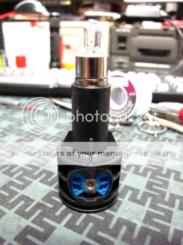
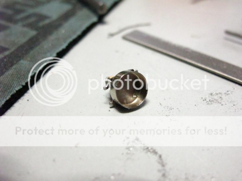
Well that's looks normal.
Hmm, what's that crap on the side ?
Some new connection, but not a FET.
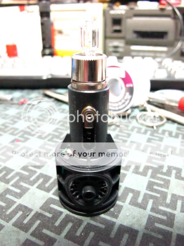
I see, a new positive connection.
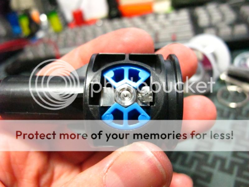
And there's something strange going on with the Negative too.
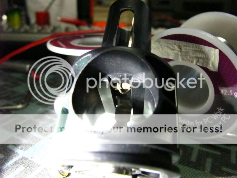
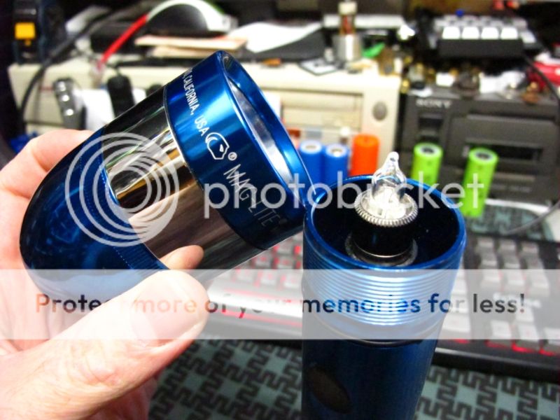
Let's look inside.
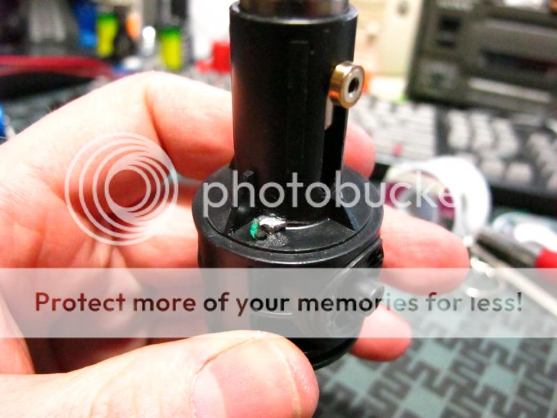
That's looks different, well it's definitely modded.
Wait, what am I looking at here ?
It's the FET !
I came up with a creative and clean why to pack a FET into a stock mag tower.

The FET in question is a P-Channel IRFR 5305.
Rated 55v 30A. Those are some some kicking numbers.
Only problem is I can't get it to light up with less then 5v at the gate,
so it's useless for the FM 4v Axial bulb running of 4 Nimh D cells I originally intended it for.
It will light up but not completely.
It does however make this mod perfect for those inclined to build a ROP.
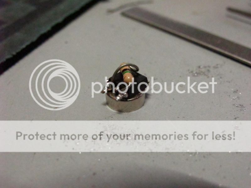
You've already seen how I prepped the FET, you'll soon understand the odd resistor placement.
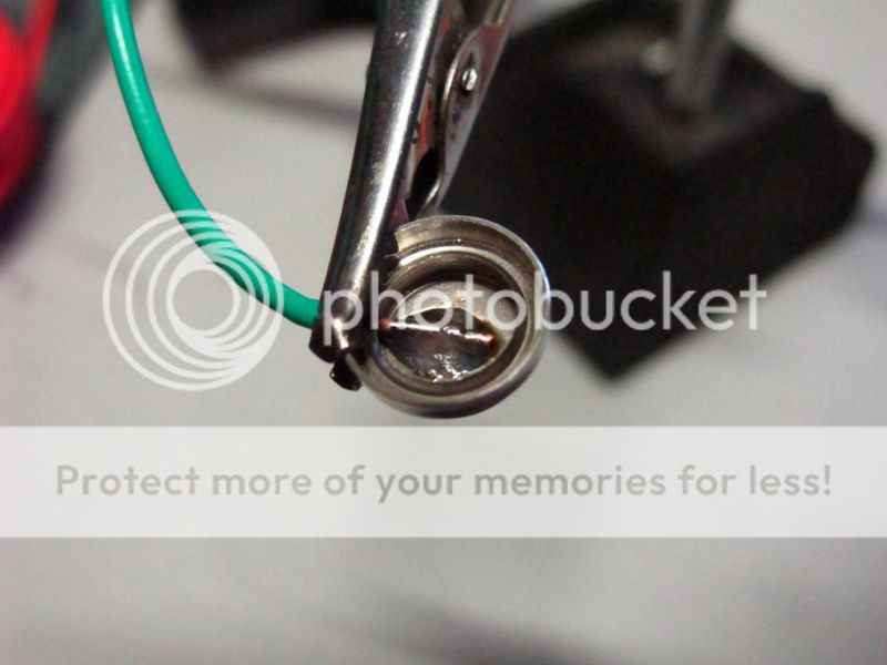
Lets move on to the negative.
That piece of scrap came out of a laptop battery pack.
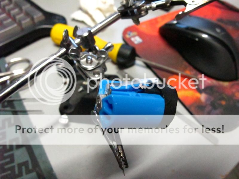
It will pass the negative control voltage to the switch.
It's cut long enough to pass over the Positive hole and sandwich under the mag switch.
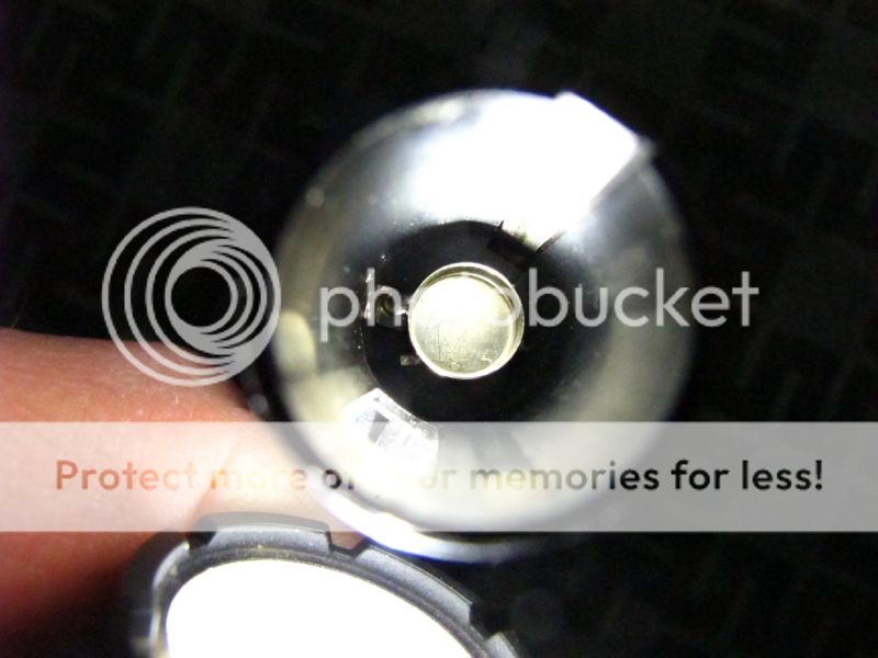
No insulation is needed the way I modded the Positive battery terminal . . . speaking of which . . .

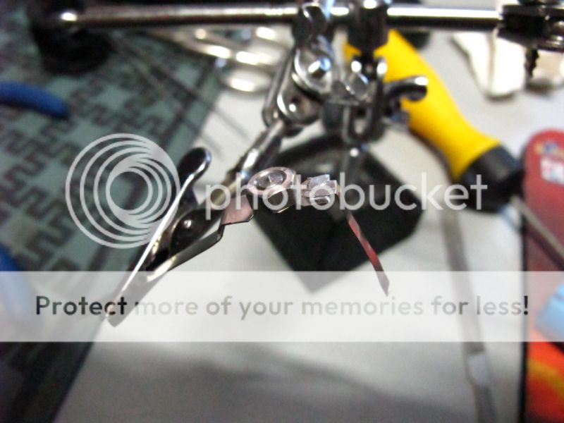
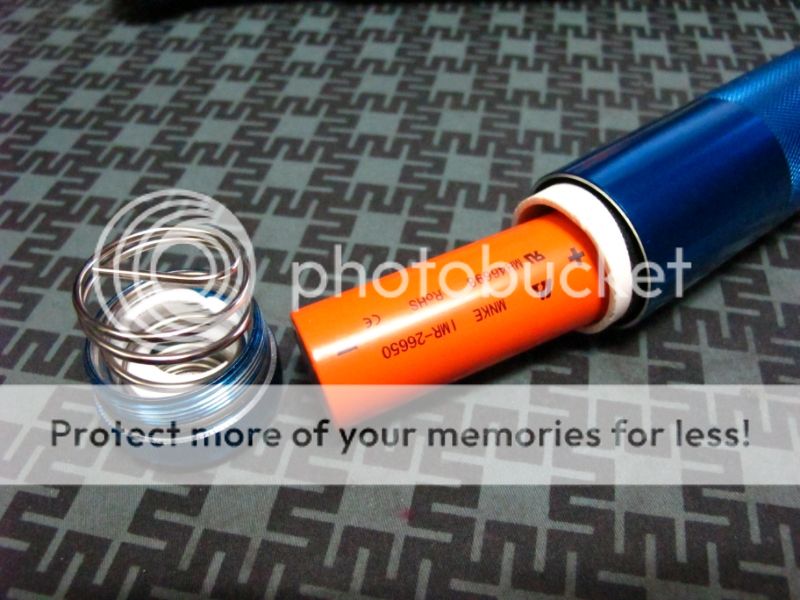
You're going to want to remove it, remove the spring, and put a slight bevel on the edge.
This will remove the bite for an easier reinstall.
I spun it in a half in chuck and hit it with a file.
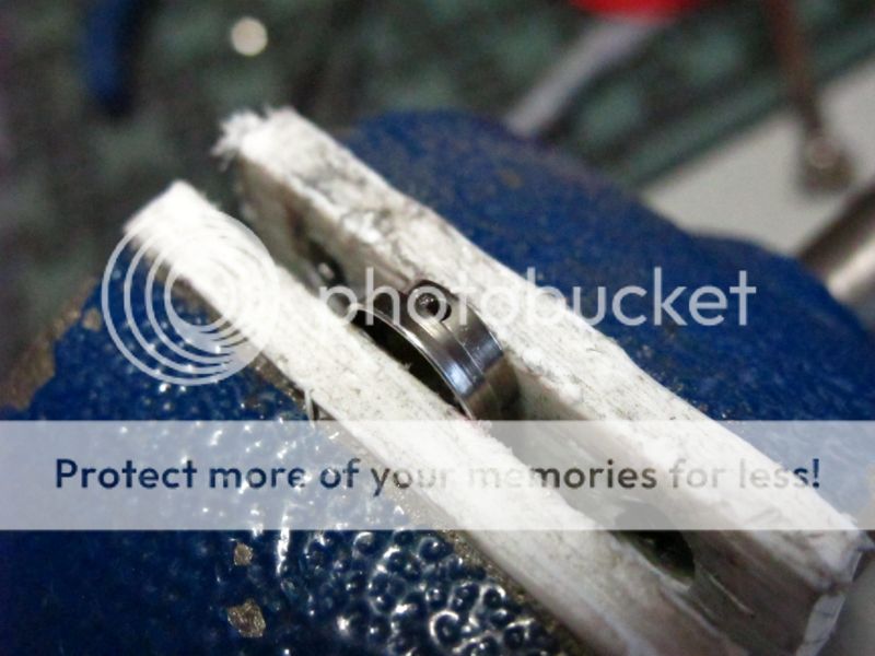
Go ahead an pop a hole in the side of it.
It'll make it easier to install a wire.
When you reinstall it upside down, it makes for a way cleaner finished look then the ol' solder a wire to the end of the spring.
This is why we bevel it. It won't go in nicely this way unless you take the edge off.

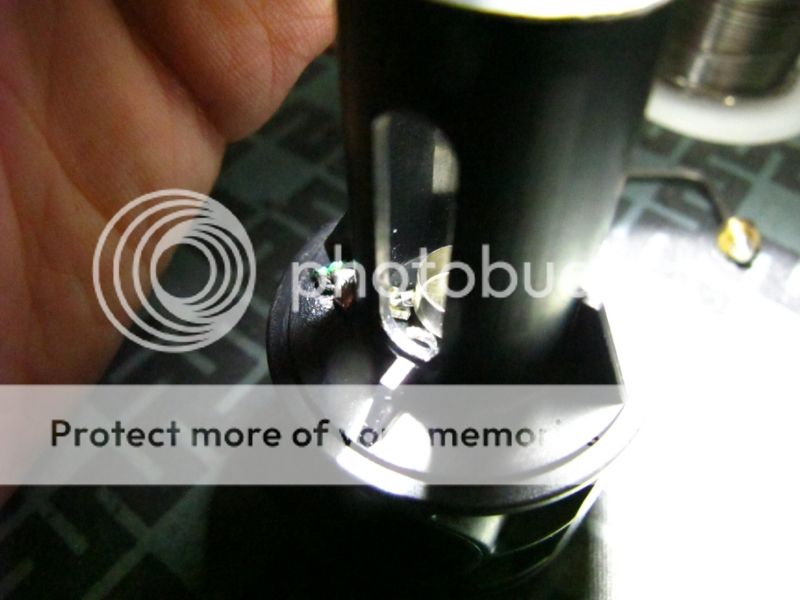
We do the usual drilling of hole to pass the new wire, but we also cut a little slit in the side of the tower base to pass this flat piece of metal.
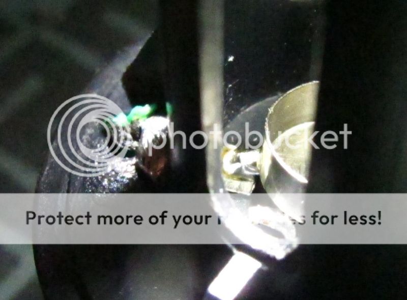
The source pin is going to sit on that flat. The new positive wire is connected to the other side.
18g solid copper wire was used. Be weary, these are tricky solder joints to make.
It's hard enough to get the tip of the iron down there to make that joint while not melting anything,
one wrong move and you'll bind the source pin to the spring cup.
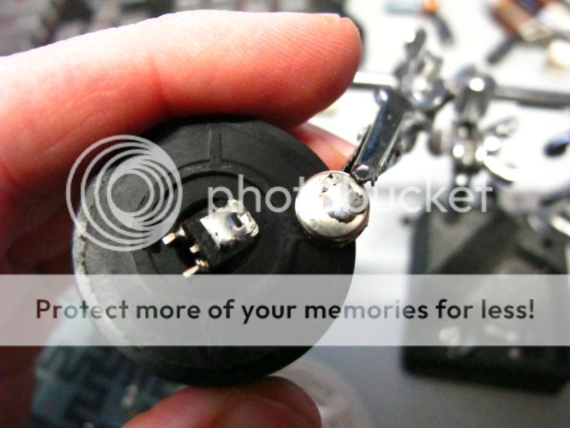
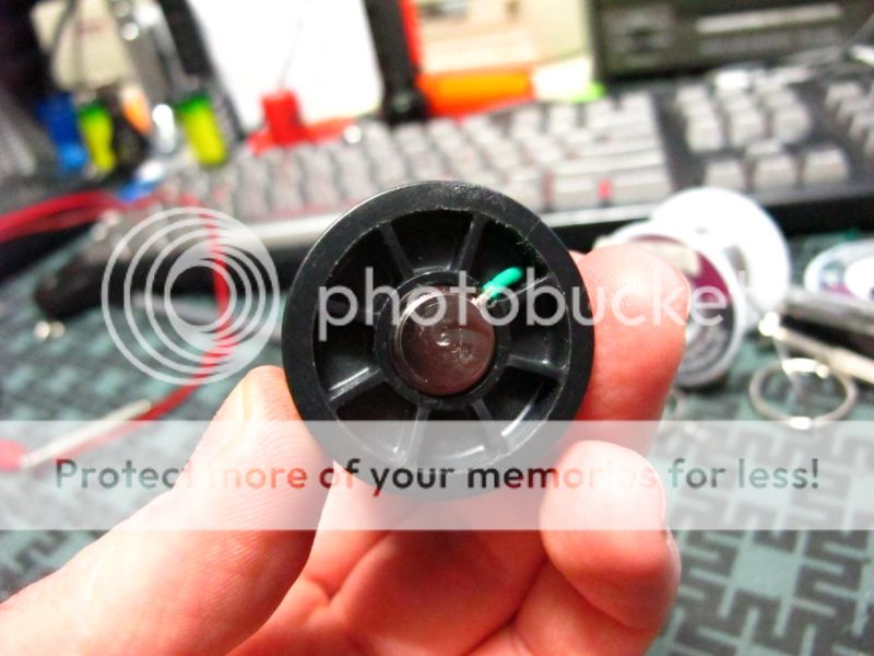
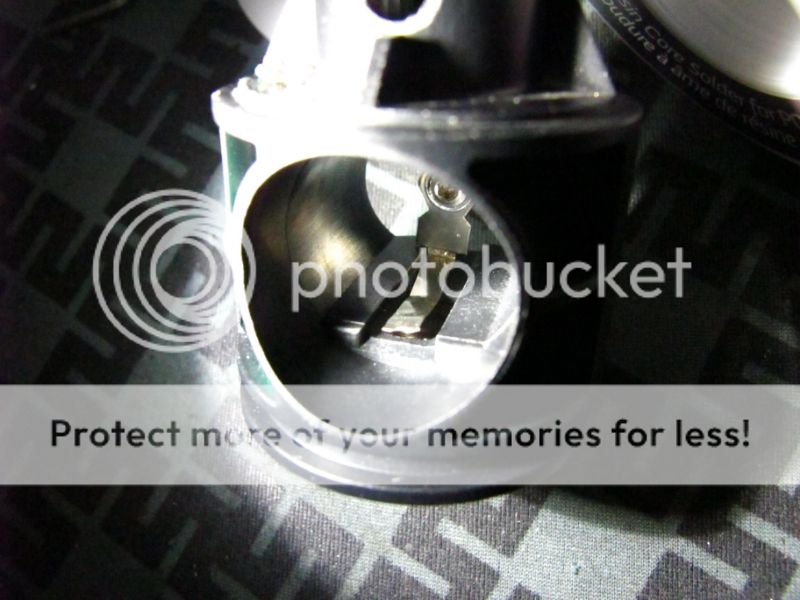
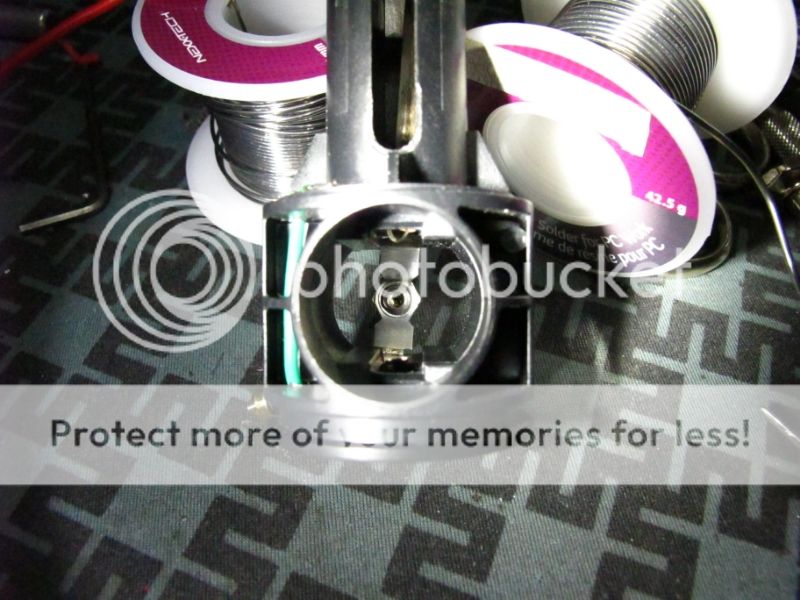
Illustrated on this cut down tower, you can see how well the little FET sits and fits in the hole.
I'm prototyping a couple other FET mods.
Now you see how I was able to cleverly mount the resistor in such a way that it's also the control signal pickup.
The lead on the resistor going to the Gate pin will also make contact with the Mag Switch.
And so now, we're pretty much done. As you can see, no Mag Switches were harmed in the making of this mod.
It just slips in there like it normally does, and can slip back out for servicing. No soldering to the switch it required, just be careful to align the bottom contact as you slip it in, or it can get pushed rearward, or down into the battery contact.
You may have to precompress to switch contact to slip it over. If done right, the negative post will span over the hole supported on either side with no risk of shorts.
Hold on, I forgot to add the crystals.
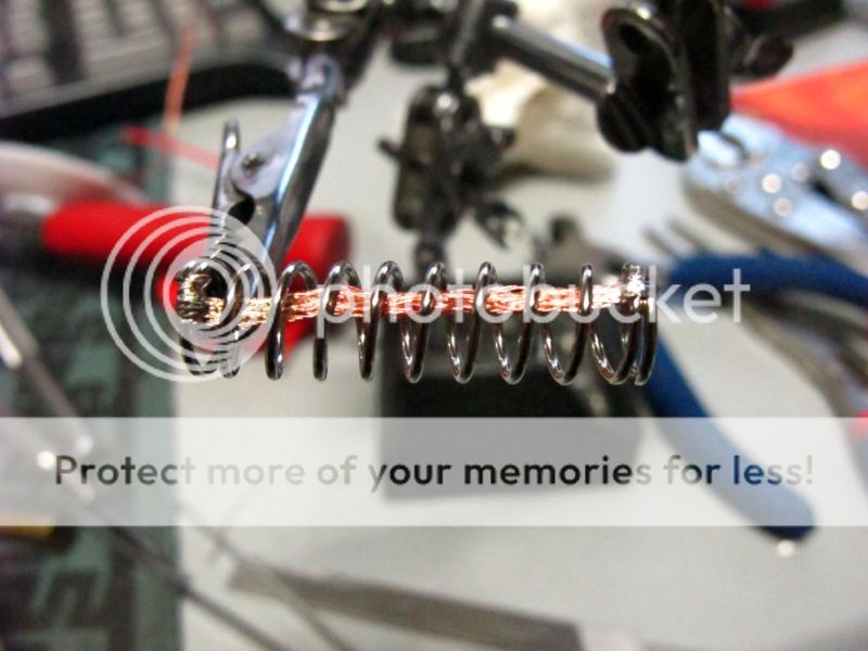
This mod would be pointless unless I fixed up the slug spring.
The wire was fused in the open space at the very tip of the coil so that the spring will still evenly sit in it's respective cups.
I filed the outside edge of the wire for a snug fit with little insertion force.
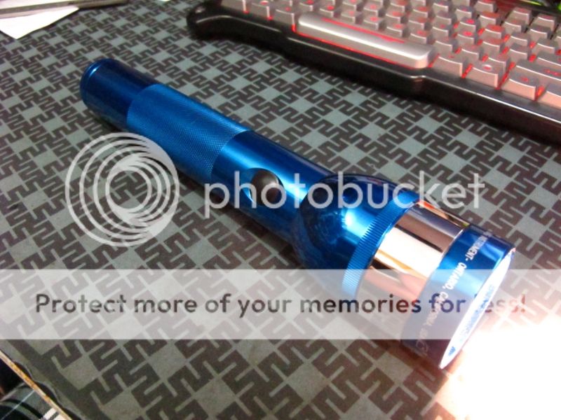
And now, the ROP . . . she goes to 11.
To be honest, I've never really been impressed with the 3853 bulb,
but the combination of this mod plus some kicking 26650 IMR cells really give it . . . . *One More!

Too bad I don't have a 3854-H bulb on hand.
IMPORTANT CONSIDERATION:
! This design uses a P-CHANNEL FET !
Not the common N-Channel FET that is abundant and used it pretty much every other FET mod.
As such, other guidelines and schematics will not apply.
A P-channel FET switches the positive side of the circuit.
An common N-Channel FET switches the negative side.
A P-FET is needed for the convenience of being able to stick it under the spring cup.
In order to execute this design with an N-channel FET you would have to reverse the polarity of the bulb contacts which is easy enough, but then you positively charge the outside of the bulb slug.
IF that Positively charged slug happens to touch your aluminum reflector, which is mounted in your negatively charged aluminum Mag Body, well . . .
If you have the same kind of Fivemega reflector as I, then the slug is directly contacting the reflector via the cam system,
so that idea is out.
Meanwhile, you could put an N-channel FET switching the negative while leaving the polarity intact, but under the same circumstances stated, contacting the reflector would bypass the switch and cause the light to come on without the use of the switch.
This could be an option that would work for Non-Cammed systems that can be aligned to prevent the slug from contacting the reflector. However, this is a completely different design. I have a really slick prototype built on this system, but for a different bulb mount that doesn't completely address this issue yet. It pretty much depends on the reflector and head having enough anodizing intact to insulate it from the body.
In conclusion, I leave you with a rough diagram of what going on:
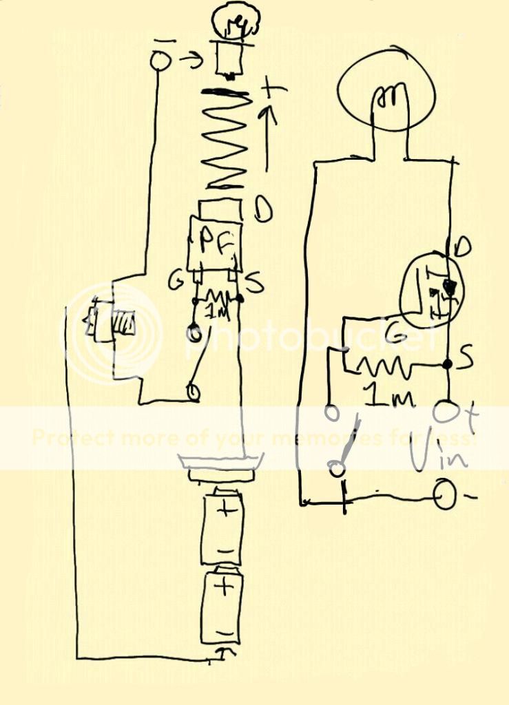
*Adding a FET switch can literally result in an increase of output over a mechanical switch.
Well that's looks normal.
Hmm, what's that crap on the side ?
Some new connection, but not a FET.
I see, a new positive connection.
And there's something strange going on with the Negative too.
Let's look inside.
That's looks different, well it's definitely modded.
Wait, what am I looking at here ?
It's the FET !
I came up with a creative and clean why to pack a FET into a stock mag tower.
The FET in question is a P-Channel IRFR 5305.
Rated 55v 30A. Those are some some kicking numbers.
Only problem is I can't get it to light up with less then 5v at the gate,
so it's useless for the FM 4v Axial bulb running of 4 Nimh D cells I originally intended it for.
It will light up but not completely.
It does however make this mod perfect for those inclined to build a ROP.
You've already seen how I prepped the FET, you'll soon understand the odd resistor placement.
Lets move on to the negative.
That piece of scrap came out of a laptop battery pack.
It will pass the negative control voltage to the switch.
It's cut long enough to pass over the Positive hole and sandwich under the mag switch.
No insulation is needed the way I modded the Positive battery terminal . . . speaking of which . . .
You're going to want to remove it, remove the spring, and put a slight bevel on the edge.
This will remove the bite for an easier reinstall.
I spun it in a half in chuck and hit it with a file.
Go ahead an pop a hole in the side of it.
It'll make it easier to install a wire.
When you reinstall it upside down, it makes for a way cleaner finished look then the ol' solder a wire to the end of the spring.
This is why we bevel it. It won't go in nicely this way unless you take the edge off.
We do the usual drilling of hole to pass the new wire, but we also cut a little slit in the side of the tower base to pass this flat piece of metal.
The source pin is going to sit on that flat. The new positive wire is connected to the other side.
18g solid copper wire was used. Be weary, these are tricky solder joints to make.
It's hard enough to get the tip of the iron down there to make that joint while not melting anything,
one wrong move and you'll bind the source pin to the spring cup.
Illustrated on this cut down tower, you can see how well the little FET sits and fits in the hole.
I'm prototyping a couple other FET mods.
Now you see how I was able to cleverly mount the resistor in such a way that it's also the control signal pickup.
The lead on the resistor going to the Gate pin will also make contact with the Mag Switch.
And so now, we're pretty much done. As you can see, no Mag Switches were harmed in the making of this mod.
It just slips in there like it normally does, and can slip back out for servicing. No soldering to the switch it required, just be careful to align the bottom contact as you slip it in, or it can get pushed rearward, or down into the battery contact.
You may have to precompress to switch contact to slip it over. If done right, the negative post will span over the hole supported on either side with no risk of shorts.
Hold on, I forgot to add the crystals.
This mod would be pointless unless I fixed up the slug spring.
The wire was fused in the open space at the very tip of the coil so that the spring will still evenly sit in it's respective cups.
I filed the outside edge of the wire for a snug fit with little insertion force.
And now, the ROP . . . she goes to 11.
To be honest, I've never really been impressed with the 3853 bulb,
but the combination of this mod plus some kicking 26650 IMR cells really give it . . . . *One More!
Too bad I don't have a 3854-H bulb on hand.
IMPORTANT CONSIDERATION:
! This design uses a P-CHANNEL FET !
Not the common N-Channel FET that is abundant and used it pretty much every other FET mod.
As such, other guidelines and schematics will not apply.
A P-channel FET switches the positive side of the circuit.
An common N-Channel FET switches the negative side.
A P-FET is needed for the convenience of being able to stick it under the spring cup.
In order to execute this design with an N-channel FET you would have to reverse the polarity of the bulb contacts which is easy enough, but then you positively charge the outside of the bulb slug.
IF that Positively charged slug happens to touch your aluminum reflector, which is mounted in your negatively charged aluminum Mag Body, well . . .
If you have the same kind of Fivemega reflector as I, then the slug is directly contacting the reflector via the cam system,
so that idea is out.
Meanwhile, you could put an N-channel FET switching the negative while leaving the polarity intact, but under the same circumstances stated, contacting the reflector would bypass the switch and cause the light to come on without the use of the switch.
This could be an option that would work for Non-Cammed systems that can be aligned to prevent the slug from contacting the reflector. However, this is a completely different design. I have a really slick prototype built on this system, but for a different bulb mount that doesn't completely address this issue yet. It pretty much depends on the reflector and head having enough anodizing intact to insulate it from the body.
In conclusion, I leave you with a rough diagram of what going on:
*Adding a FET switch can literally result in an increase of output over a mechanical switch.
Last edited:
") What sort of runtime are you getting with those IMR cells? I've got several packs of ROP Low/Hi bulbs as well as quite a few loose ones that i've gotten here and there. (mostly lows from people that only used their hi bulb and donated me their low because I sometimes value runtime over output
What sort of runtime are you getting with those IMR cells? I've got several packs of ROP Low/Hi bulbs as well as quite a few loose ones that i've gotten here and there. (mostly lows from people that only used their hi bulb and donated me their low because I sometimes value runtime over output