TrustFire TR-J1

JoelSim

Newly Enlightened
Joined
Aug 14, 2011
Messages
48
Location
Norway
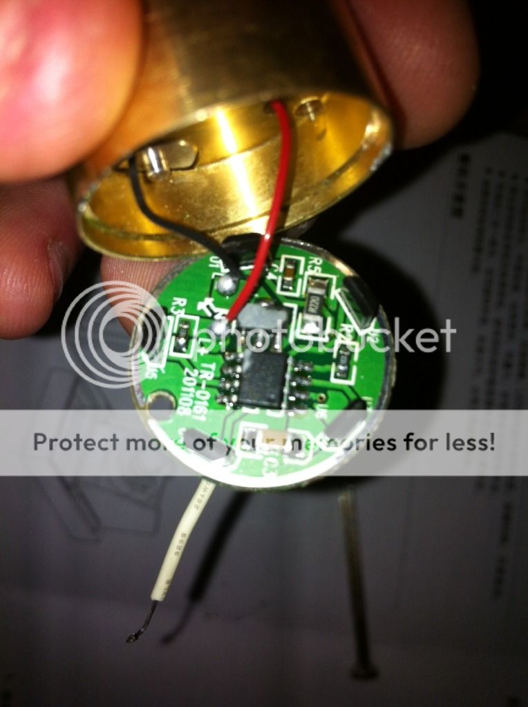
You would need to remove the tail cap and use an amp meter to measure current between the battery and the light's case. So get a multi meter and set it up to measure amps. Touch one of the leads to the back side of the battery and one to the flash light's barrel where it does not have anodizing. The light should turn on (once the switch is turned on) and the meter should show amps.

Now that you put it like that it indeed seems perfectly logical. Thanks for that.

Just got the batteries on charging to full now and I'll run some tests.

Moving on to some other observations.

It indeed seems that consistency during manufacture/assembly is not high on the list. Between Doc Ed's example and my two I am seeing some differences.

One point between my two when breaking them down was the difference that one had quite a lot of aluminium and plastic shavings from the machining process and quite an excess amount of silicone grease over almost every surface. The other was quite free of shavings and with a much more reasonable amount of greasing.

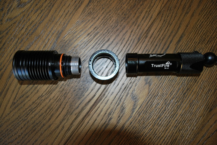
Then there was the o-rings.... Doc Ed mentions having only one at the light head end (plus the friction ring). This differed between my two. One came with only one and the other with two:
DSC_0612.JPG


Also I think that between both lights and a total of 7 of the black o-rings all of them have some small amount of damage to them. This is leaving me somewhat sceptical as to whether they will in fact do their job. All o-rings are super soft also which I am a touch sceptical of...not sure how they will handle pressure. (feel free to comment for or against that train of thought). All in all starting to think that switching out o-rings could be a smart move.

@ Doc Ed: I know you pot tested yours to 65m. Was this using all the original o-rings? Did you notice any damage to any of yours when you received it?

Also a +1 to Doc Ed's idea of a dot of glue or something on the little magnet for switching mechanism. They do indeed fall out quite easily. Currently I have just dabbed a little silicone grease on the bottom of it :)

Over all though I am still quite impressed with these little lights. Will be interesting to see the current draw results soon.

Cheers,
Joel

P.S. Note to self (and others) threads on tail cap end are rather sharp, got a nice little slice on my thumb from it :crazy: But something to be aware of I guess when placing o-rings back in place. More meaning being aware or not slicing the o-rings......
 
Last edited:

Doc Ed

Newly Enlightened
Joined
Oct 20, 2010
Messages
53
Location
Manila, Philippines

Are those hall-effect sensors on the periphery? Sweet! Now I wanna take mine apart as well! :D

And what chip does the driver use? And the white wire attaches to what?

I also note a tab near the LED star. I take it this is to align the pill with a corresponding groove in the head to ensure the sensors are properly aligned with the indicator marks on the outside. Nice to see it looks relatively robust :D Is there a similar method of aligning the driver when you reattach it to the pill so the modes positions remain the same?

@JoelSim: I guess QA isn't really a strong suit with them. I can sort of understand possible differences between your light and mine (maybe different batches) but then to see those same differences between two lights of yours which most likely came from the same batch is really a weird one. I think I really will add that extra o-ring. I didn't try to lever off the existing o-rings to check the durometer. I conducted my pressure test using the stock o-rings, as I noted no damage on them and the amount of lube on them was okay. Do both of your lights have the soft o - rings?
 
Last edited:

JoelSim

Newly Enlightened
Joined
Aug 14, 2011
Messages
48
Location
Norway
@JoelSim: I guess QA isn't really a strong suit with them. I can sort of understand possible differences between your light and mine (maybe different batches) but then to see those same differences between two lights of yours which most likely came from the same batch is really a weird one. I think I really will add that extra o-ring. I didn't try to lever off the existing o-rings to check the durometer. I conducted my pressure test using the stock o-rings, as I noted no damage on them and the amount of lube on them was okay. Do both of your lights have the soft o - rings?

Yeah I see your point about the different batches, but agreed that it's a bit strange between my two.

Yes both lights have the "soft o-rings". Whether they actually are soft or if I just consider them to be is anyone's guess though I figure. But most of them look like they have a slither missing off them and one in particular looks just a little deformed in general. Bit of a shame, but.....

Time to duck to the shops and see if I can find some new o-rings to do the job though I think.

Cheers,
Joel.
 

hanachan

Newly Enlightened
Joined
Nov 21, 2008
Messages
115
Location
Japan
sucnip, thank you for the photo of the 'driver'.

it looks very simple, consisting of five hall-ic, one maybe FET and one micro controller (AVR or PIC??).
IMO strictly speaking, it is NOT driver but direct driving with PWM.
the micro controller may sense hall ic outputs and do PWM on LED current via FET (high:100%, mid :50%, low 10%).
if so, we should NOT use a good battery with very low internal resistance to avoid burning LED
and NOT use non protected battery to avoid over discharge in this light.
there may be a very little current at OFF mode.
 

Doc Ed

Newly Enlightened
Joined
Oct 20, 2010
Messages
53
Location
Manila, Philippines
That would probably explain the wide spread in the measured tail-cap voltages. It is my understanding that in direct drive, as voltage decreases, so does current (please correct me if erroneous). However, I didn't quite notice that large of a dimming effect in your beam-shots in your other thread. Although, it does jive with your findings of being able to drain the battery to 2.75v without any indicators like blinking and such. I guess its back to the multi-meter to measure currents at various discharge states.

@Sucnip: I assume that the pill is easy to remove after unscrewing the ring from the front half? Going to try this myself tomorrow :D
 
Last edited:

350xfire

Flashlight Enthusiast
Joined
Aug 14, 2008
Messages
1,229
Location
Texas
I guess QA isn't really a strong suit with them.

Hahahaha.... When you pay employees $1 a day to assemble something, you can bet you will get what you pay for... As with anything cheap from China, you may need to rework it to make it do what it was intended to!
 

JoelSim

Newly Enlightened
Joined
Aug 14, 2011
Messages
48
Location
Norway
Just checked the tail cap current draw on my two and they are virtually identical.

With fresh charged batteries- Trustfire 3.7v 2400mAh

4.2v- Hi-1.85 Med-0.91 Low-0.19
4.2v- Hi-1.83 Med-0.91 Low-0.19

I just used my multi meter as is. No using thicker wires(as was suggested earlier)or anything like that.
 

sucnip

Newly Enlightened
Joined
Dec 14, 2005
Messages
53
Location
Sydney, Australia
Are those hall-effect sensors on the periphery? Sweet! Now I wanna take mine apart as well! :D

Yup.

And what chip does the driver use? And the white wire attaches to what?

Not sure what the driver is. There's a small microprocessor and a current limiting chip. The white wire attaches to the positive terminal of the battery via the white plastic disc.
 

sucnip

Newly Enlightened
Joined
Dec 14, 2005
Messages
53
Location
Sydney, Australia
@Sucnip: I assume that the pill is easy to remove after unscrewing the ring from the front half? Going to try this myself tomorrow :D

It wasn't too bad. Remove the screw down ring with a pair of needle nose pliers. The pill will fall forward a few cm and get caught by the white wire connected to the plastic plug. I rotated the pill 90 degrees and used a small screw driver to push the white disc out. Then I unsoldered the white wire from the disc and the pill fell out.

There are two solder spots where the board attaches to the pill. Simply use the hold in the PCB and the alignment disk to make sure you put it back together the same way. No problems with the modes when reassembling the light. Good luck!
 

DIWdiver

Flashlight Enthusiast
Joined
Jan 27, 2010
Messages
2,725
Location
Connecticut, USA
sucnip, thank you for the photo of the 'driver'.

it looks very simple, consisting of five hall-ic, one maybe FET and one micro controller (AVR or PIC??).
IMO strictly speaking, it is NOT driver but direct driving with PWM.
the micro controller may sense hall ic outputs and do PWM on LED current via FET (high:100%, mid :50%, low 10%).
if so, we should NOT use a good battery with very low internal resistance to avoid burning LED
and NOT use non protected battery to avoid over discharge in this light.
there may be a very little current at OFF mode.


+1

In direct drive lights, the current measurement will be very much dependent on the meter and the leads you use (mostly the meter, unless you have really poor leads). The only way to get a really accurate measurement is to use a short piece of heavy wire and a clamp-on ammeter. Or a low-impedance shunt and the meter on millivolt range.

And yes, the light will begin to diminish as soon as you turn it on, and will keep diminishing until you turn it off or it goes out.
 

Doc Ed

Newly Enlightened
Joined
Oct 20, 2010
Messages
53
Location
Manila, Philippines
Joelsim, could you post a photo of your o-rings? Does it just seem like there's a faint seam? I got my 2nd light in the mail today. More or less same findings as the first: Minimal to no swarfs, same configuration of o-rings as previously noted. Did see faint seams on the o-rings though I didn't bother to remove them to check their durometer. Put the new light in the pressure pot and tested down to 75 meters with a gradual ascent up to 28 meters over a span of 30 minutes (ie there's a small leak somewhere in my pot ;) ) - no leaks! Tissue paper I kept in the battery tube stayed nice and dry. Maybe you won't need to change out your o-rings after all.

Was also able to test out different battery types with different voltages. The findings were consistent with the notion that this is a direct drive light with PWM. On high, at 4.08v, I was getting around 1.98A for both lights, 3.8V was 1.6A for both, and at 3.6v, around 1.4A.
 

JoelSim

Newly Enlightened
Joined
Aug 14, 2011
Messages
48
Location
Norway
Joelsim, could you post a photo of your o-rings? Does it just seem like there's a faint seam? I got my 2nd light in the mail today. More or less same findings as the first: Minimal to no swarfs, same configuration of o-rings as previously noted. Did see faint seams on the o-rings though I didn't bother to remove them to check their durometer. Put the new light in the pressure pot and tested down to 75 meters with a gradual ascent up to 28 meters over a span of 30 minutes (ie there's a small leak somewhere in my pot ;) ) - no leaks! Tissue paper I kept in the battery tube stayed nice and dry. Maybe you won't need to change out your o-rings after all.

Was also able to test out different battery types with different voltages. The findings were consistent with the notion that this is a direct drive light with PWM. On high, at 4.08v, I was getting around 1.98A for both lights, 3.8V was 1.6A for both, and at 3.6v, around 1.4A.

Usually it would be no problem to post pics, but I'm in transit on my way to Malta. So I'll have to do it in a week or so when back. Sorry about that.

Meanwhile it's going to be a little 'trial by fire/water'. I've not switched out the o-rings, so we'll see what happens.

Little bit comforting to read your results tho. Thanks for that.

To be continued......
 

Doc Ed

Newly Enlightened
Joined
Oct 20, 2010
Messages
53
Location
Manila, Philippines
I'm sure they'll be okay :D At any rate, I forgot to include above that I also checked my 1st light, and the o-rings also had the faint seam in them as well.
 

DIWdiver

Flashlight Enthusiast
Joined
Jan 27, 2010
Messages
2,725
Location
Connecticut, USA
It's not unusual to be able to see the 'seam' on o-rings. Technically it's called 'flash' or 'mold flash'. Almost every o-ring I've seen has some detectable flash. It doesn't cause a problem in most applications. Apple Rubber does mention it in their book, and they can create o-rings with axial flash, but I've never seen much discussion about it. I'm guessing that only in the most critical applications is it important.

Most o-rings seal in the radial direction (between inner and outer diameter), which is right where the flash is on most o-rings. It seems to work. I would reject a ring with excessive flash, but the compression in most applications seems to overcome a small amount of flash.
 

gasdiver

Newly Enlightened
Joined
Jun 17, 2011
Messages
22
Technically, this seam is called a "parting line". It's where the two halves of the mold meet. Flash is created when the polymer flows between the two halves of the mold. Parting lines are unavoidable and exist on every type of injection molded part, including o-rings. Flash, on the other hand, is a result of a poor quality or worn out mold. Flash is definitely a quality issue. It can be trimmed off and not effect the function of the part, but trimming it adds cost in the manufacturing process. If you get o-rings with any significant amount of flash, I would look for a different source.

BTW, I used to work for GE Plastics and ran a group of engineers who performed computer-aided mold filling and structural analysis. We assisted GE's customers with tool design and structural integrity of their plastic parts. My master's thesis in graduate school was entitled "Stiffness determination of hyper-elastic o-ring seals using the finite-element method". Thank god I've forgotten most of that crap!
 

JoelSim

Newly Enlightened
Joined
Aug 14, 2011
Messages
48
Location
Norway
Ok....so back to reality after a good week of diving.

Have some positive and some negative regarding this/these lights. Didn't take them below 42m, but seemingly no floods or anything like that which is good.

The positive:

Worked great as a light for travelling and not doing any seriously light craving tasks. Nice and small, bright enough to do what we asked of it.


The negative:

My light worked fine...my wife's on the other hand, not so much.
Her light decided at one point (approx. 38-40m) to no longer want to turn off. Turning it right through all settings then managed to turn it off. After this the light has never quite functioned properly again. It works, but flickers and drops in and out. A bit of a tap fixes this temporarily but the problem returns. I tried switching my battery into it, just to check, and the problem persisted :mecry:

Does anyone have any thoughts about this issue???

Thinking that I am going to be sending of an e-mail and asking for a replacement.

Back to the o-ring topic.....

Seemingly even with the imperfections I noticed on the o-rings they seem to have worked just fine, so that's not all bad. The two above posts are good to know and read, although the 'seems' or 'parting lines' or even 'flash' is not what I noticed or was referring to. I noticed what looks like pieces have actually been sliced off the o-ring/s. I will break the lights down and see if I can get some pics for illustration of this (I have sick child on my hands at the moment, but will try and get it done ASAP).
Either way as I said the above posts are good info and good to know.
@gasdiver: Sorry for dragging up those painful memories for you, lol.

To be continued......
 

JoelSim

Newly Enlightened
Joined
Aug 14, 2011
Messages
48
Location
Norway
Not completely off topic but a little......

Upon breaking down one of these lights again and doing some measurements I got to thinking. Off the top of my head it seems that one of the aHorton aspheric lenses could fit quite nicely in this light head with very little modifying at all!?!?

Does anyone have one of these lights and an aspheric laying around that they would be willing to experiment with?? (Unfortunately I have only one of these aspheric lenses here and it's in my can light head which I'm in no hurry to pull apart again.)

Would there be any point in this??
 

Doc Ed

Newly Enlightened
Joined
Oct 20, 2010
Messages
53
Location
Manila, Philippines
A user on a different board encountered similar problems. He traced the fault to a possible inadvertent loosening of the front bezel allowing some water to come in and dampen the electronics. Perhaps disassembly and proper drying might rectify the issue.

Also checked my photos... there is a small shelf within the head that you could rest an aspheric on and still maintain the air gap in front :D Not sure if the distance is enough to focus the beam properly though... An interesting project :D

Any photos/shots of the light in action in Malta?
 

jeffkruse

Newly Enlightened
Joined
May 19, 2010
Messages
75
I bought one of these. On the first dive to 40' it flooded. I got my money back with no hassel and was able to keep the light. Bummer though the battery was toast! I rinsed the light and tried it again. I think the lense was loose the first time. No leaks and it worked. But it is unreliable. It sometimes turns on and sometimes turns off. It may be a good backup light if you get a good one. I love the size. It's bright but I think I will have to put up with the size of the DRIS 3C cell "1000" lumen light. Damn, I so wanted this light to work.
 
Top