Doc Ed
Newly Enlightened
Was the light malfunctioning (sometimes on, sometimes off) prior to getting flooded?

I decided to give me light a "rice bath" last night. ( Heat rice in the oven until hot and then put the rice and light in a sealed container overnight to draw moisture out of the light. )
Success! All of the positions of the bezel ( low, med, high, strobe ) now work. Since I understand the cause of the leak (user stupidity) I feel comfortable taking it on a dive today. I'll let you know what I think of it.
Ok....so back to reality after a good week of diving.
The negative:
My light worked fine...my wife's on the other hand, not so much.
Her light decided at one point (approx. 38-40m) to no longer want to turn off. Turning it right through all settings then managed to turn it off. After this the light has never quite functioned properly again. It works, but flickers and drops in and out. A bit of a tap fixes this temporarily but the problem returns. I tried switching my battery into it, just to check, and the problem persisted :mecry:
Does anyone have any thoughts about this issue???


Now what you've been waiting for- the driver:
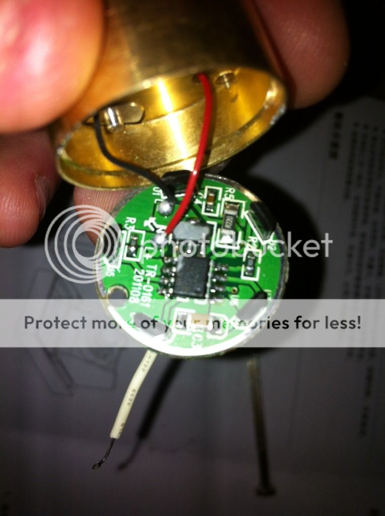
if you can read the text on the chip, can you post it, then we can have a look in the datasheet. the chip often uses a sense resistor to regulate the current, so it is often possible to do this. The max output depends on the chip and possibly some other components, but going from 2.8 to 3A shouldn't be a problem for the driver.
Johan
That's assuming the posted measurements were accurate, and my guessing is accurate.
After your above comment it got me to thinking again about an earlier post that mentioned using some shortened wires between the multi-meter and the light whilst taking the current readings. So I thought I would give that a go and see the result.
The result was a bigger difference than I had expected. This time around I got approx. 2.2A on both my lights (instead of around 1.8A).
Starting to think that messing with the driver is going to result in nothing but a bang (or at least something burning up).
Perhaps it is wise for me to leave them as they are (more or less....aside from removing the optic and moving the led forward closer to the lens on a heatsink).
Cheers again, Joel.
Blindeye, I hope you don't mind me adding my input to your review.
CONSTRUCTION:
I Got mine in the mail todayFirst impressions: Seemed relatively well built - nice and solid. On removing the head, there were one or two swarfs, but otherwise it looked great. The cooling ridges on the head are not overly-done as seen on some other dive lights. The removable stainless steel attack crown was the first to come off. Granted, it looks like it could do some serious damage if ever used for its intended purpose..............................!