Klem
Enlightened
Now it's finally finished I thought I'd combine the photos and ideas from a few previously threads into a single 'How to'.
Thanks everyone for your ideas in this.
It's a solid compact torch, more powerful than the 'Ugly Torch' but still fits in a BC pocket.
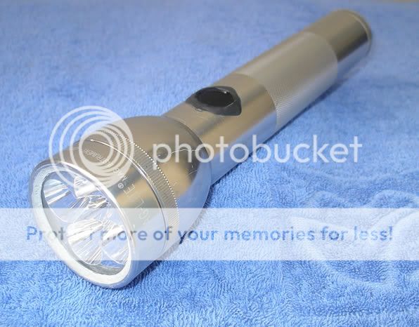
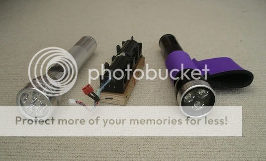
It's a 2D Maglite with a DX 1200 lumen 'drop-in'...Using 5*Cree XR-E run at about 16watts. Batteries are 2* D Cell Li-ion (7.2V 5Ah gives 2+hrs run time). Switch is a piezo connected to a toggle circuit.
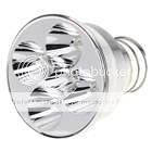
The drop-in is this one found here, http://www.dealextreme.com/details.dx/sku.35241
The Body
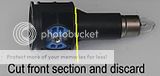
Take a 2D Maglite and remove the switch barrel. Remove the rubber switch cover and use a 2mm Allen key to release the barrel. This is the only way so don't try coming in from the front on that circlip, you'll never get it out. Slide the barrel out the back. Cut off the narrow tube section of the barrel and discard. Push out the blue plastic insert and discard the switch mechanism. Hacksaw the blue insert in half, to free up space for the piezo. Cut short the long silver flat lead and solder a cable to what's left of it. This will be your negative take-off forward of the batteries. Solder a positive lead to the metal positive contact inside the barrel. Return the blue section to the barrel and permanently glue with epoxy.
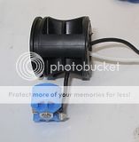
Reinsert the modified barrel back into the Maglite tighten in place with the allen key. Glue a 16mm piezo switch into the space left. Before you glue shorten the legs and solder two leads to the legs. I used 2-part metal epoxy to glue the piezo into the Maglite (Devcon). Run all four leads forward through the convenient hole in the barrel.
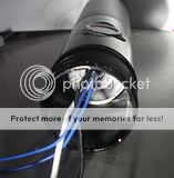
So, you now have 2 leads from the switch and the positive and negative leads from the battery.
The Switch Circuit
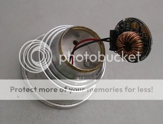
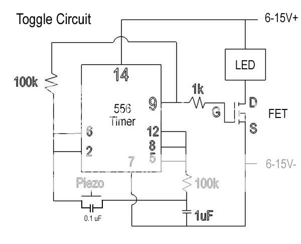
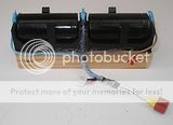
The toggle circuit for the switch is made from a few parts; including a 556 timer chip and a logic FET. I used the following circuit.
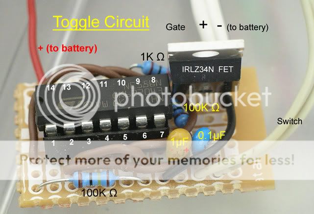
Make the board fairly compact as this needs to slide into the space between the piezo barrel and the head.
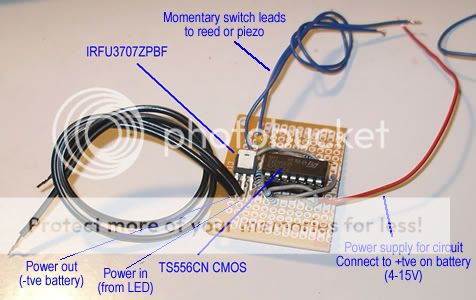
In the photo above the FET is the IRLZ34N, which is a TO-220 size part. You can use smaller FETs and make the board more compact. For example, in the photo below it is a IRF3707 in a smaller I-Pak size.
The Head
The drop-in and the Maglite head need to be machined so they fit. No way round this I'm afraid and so you'll need access to a lathe.
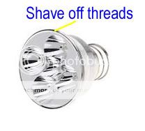
Start by shaving the threads off the drop-in to the same ID as the Maglite
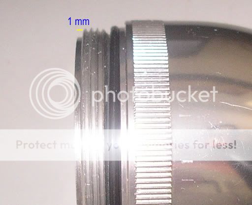
Shave the inside of the head as in the photo below. Shave shorter the Maglite bezel thread...This will make the drop-in seat proud to the front, and so when you screw the bezel on it pushes the drop-in back hard against the Maglite, which helps with heat transfer, adds internal support to the lens (to resist water pressure), and keeps it from rattling around inside.
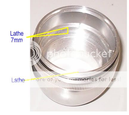
In this photo you can see by shaving the thread the drop-in sits 1mm proud.
The Maglite head is now semi-permanently glued to the body by polyeurathane sealant (Sikaflex Marine). You will not need to open this again. Check that it all fits together before glueing.
The lens
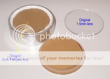
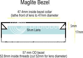
The lens can be glass or synthetic. I've used both on Maglite heads and they both work. In this latest torch I used a 6mm piece of Perspex
The lens is actually 6mm thick, but if you carefully cut a 3mm ridge on a lathe you can sit some of this thickness out the front of the bezel, leaving a thinner amount for screwing the bezel onto the Maglite threads. I've glued both the inside and outside gaps and when it's all done you peeling off the protective brown paper.
The bezel is screwd onto the Maglite head and sealed with a bead of silicone sealant (Silastic). I discard the three factory O rings on the Maglite. I replace one at the back of the handle with a thicker one... to access the battery compartment. The other two seals may as well be semi-permanent as you probably won't need to open them again.
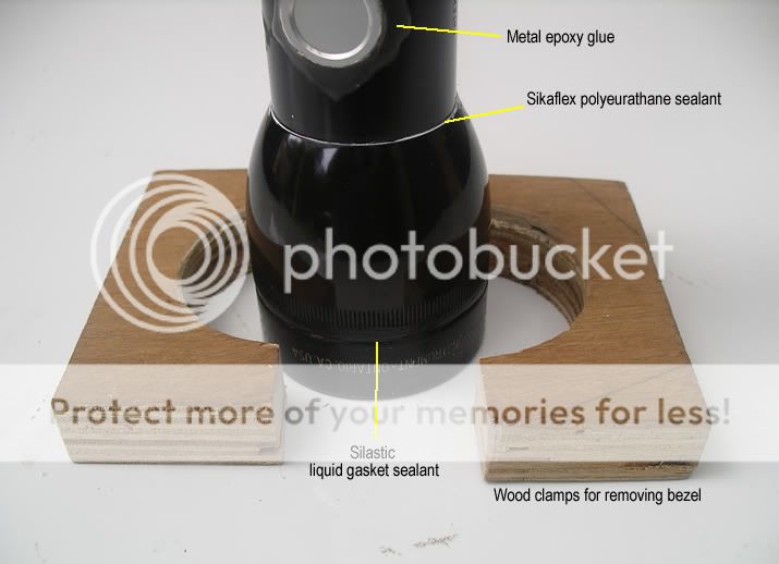
Using silicone gasket sealant for the bezel instead of a stronger glue means it can be 'cracked' open if ever you need to service the front section. I made a couple of wood clamps for this; A square of wood holed with a hole saw and cut in half. Good for an even grip in the vise and won't scratch the finish or crack the waterproof seal.
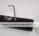
The Back End
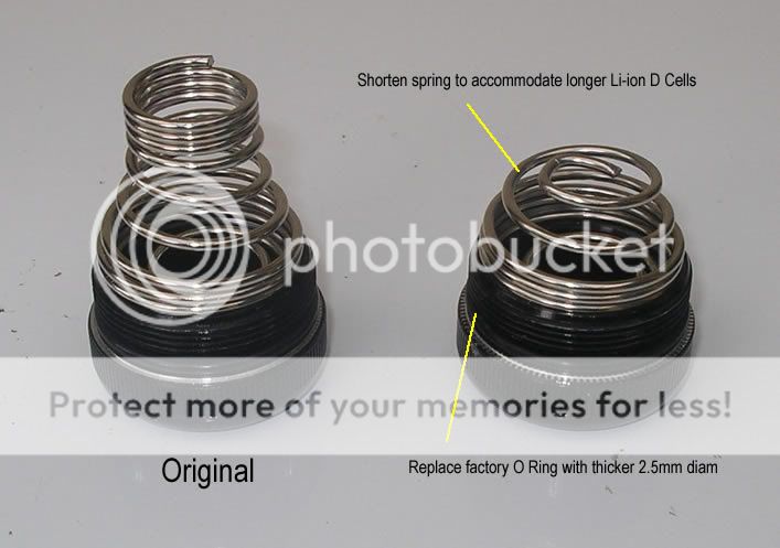

The back end. You need to shorten the spring as in the picture. D Cell Li-ions are slightly longer than normal D Cells. The O ring needs to be upgraded to a thicker 2.5mm one. As the toggle circuit chews a few milliamps I leave the back end slightly cracked to open the circuit and save the batteries. Batteries have a charging bed with leads for both balance charging, and normal fast charging. Don't forget they are unprotected so don't mix up the polarity in or out of the torch!
On an earlier torch I fitted a built-in Li-ion protection circuit, but it seems they only work to protect from over discharge if you can connect both cells individually to the circuit. With individual D Cells stacked in the handle you can't do this so I'm just mindful of the time and don't go beyond 2 hours without re-charge.

Extras
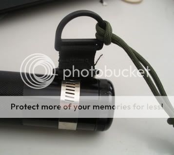
If you like to attach your torch you can always use a hose clamp (saves drilling a hole into the torch and so minimises potential flooding).
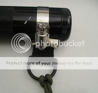
Or you can use a hands free wrist band. 20 minutes with a hand-sticher and some old wetsuit material.
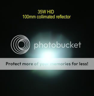
Some comparison beamshots, the drop-in is the bottom-right (I made the mistake of labelling it '5*XP-G', but it should be '5*XR-E').


I've made a few torches in my time and this would have to be the most solid. Maglites are a perfect host for a dive torch, and great for heat sink/dissipation, and this one sits in your BC pocket.
Hope this is of some help to someone.
Thanks everyone for your ideas in this.
It's a solid compact torch, more powerful than the 'Ugly Torch' but still fits in a BC pocket.
It's a 2D Maglite with a DX 1200 lumen 'drop-in'...Using 5*Cree XR-E run at about 16watts. Batteries are 2* D Cell Li-ion (7.2V 5Ah gives 2+hrs run time). Switch is a piezo connected to a toggle circuit.
The drop-in is this one found here, http://www.dealextreme.com/details.dx/sku.35241
The Body
Take a 2D Maglite and remove the switch barrel. Remove the rubber switch cover and use a 2mm Allen key to release the barrel. This is the only way so don't try coming in from the front on that circlip, you'll never get it out. Slide the barrel out the back. Cut off the narrow tube section of the barrel and discard. Push out the blue plastic insert and discard the switch mechanism. Hacksaw the blue insert in half, to free up space for the piezo. Cut short the long silver flat lead and solder a cable to what's left of it. This will be your negative take-off forward of the batteries. Solder a positive lead to the metal positive contact inside the barrel. Return the blue section to the barrel and permanently glue with epoxy.
Reinsert the modified barrel back into the Maglite tighten in place with the allen key. Glue a 16mm piezo switch into the space left. Before you glue shorten the legs and solder two leads to the legs. I used 2-part metal epoxy to glue the piezo into the Maglite (Devcon). Run all four leads forward through the convenient hole in the barrel.
So, you now have 2 leads from the switch and the positive and negative leads from the battery.
The Switch Circuit
The toggle circuit for the switch is made from a few parts; including a 556 timer chip and a logic FET. I used the following circuit.
Make the board fairly compact as this needs to slide into the space between the piezo barrel and the head.
In the photo above the FET is the IRLZ34N, which is a TO-220 size part. You can use smaller FETs and make the board more compact. For example, in the photo below it is a IRF3707 in a smaller I-Pak size.
The Head
The drop-in and the Maglite head need to be machined so they fit. No way round this I'm afraid and so you'll need access to a lathe.
Start by shaving the threads off the drop-in to the same ID as the Maglite
Shave the inside of the head as in the photo below. Shave shorter the Maglite bezel thread...This will make the drop-in seat proud to the front, and so when you screw the bezel on it pushes the drop-in back hard against the Maglite, which helps with heat transfer, adds internal support to the lens (to resist water pressure), and keeps it from rattling around inside.
In this photo you can see by shaving the thread the drop-in sits 1mm proud.
The Maglite head is now semi-permanently glued to the body by polyeurathane sealant (Sikaflex Marine). You will not need to open this again. Check that it all fits together before glueing.
The lens
The lens can be glass or synthetic. I've used both on Maglite heads and they both work. In this latest torch I used a 6mm piece of Perspex
The lens is actually 6mm thick, but if you carefully cut a 3mm ridge on a lathe you can sit some of this thickness out the front of the bezel, leaving a thinner amount for screwing the bezel onto the Maglite threads. I've glued both the inside and outside gaps and when it's all done you peeling off the protective brown paper.
The bezel is screwd onto the Maglite head and sealed with a bead of silicone sealant (Silastic). I discard the three factory O rings on the Maglite. I replace one at the back of the handle with a thicker one... to access the battery compartment. The other two seals may as well be semi-permanent as you probably won't need to open them again.
Using silicone gasket sealant for the bezel instead of a stronger glue means it can be 'cracked' open if ever you need to service the front section. I made a couple of wood clamps for this; A square of wood holed with a hole saw and cut in half. Good for an even grip in the vise and won't scratch the finish or crack the waterproof seal.
The Back End
The back end. You need to shorten the spring as in the picture. D Cell Li-ions are slightly longer than normal D Cells. The O ring needs to be upgraded to a thicker 2.5mm one. As the toggle circuit chews a few milliamps I leave the back end slightly cracked to open the circuit and save the batteries. Batteries have a charging bed with leads for both balance charging, and normal fast charging. Don't forget they are unprotected so don't mix up the polarity in or out of the torch!
On an earlier torch I fitted a built-in Li-ion protection circuit, but it seems they only work to protect from over discharge if you can connect both cells individually to the circuit. With individual D Cells stacked in the handle you can't do this so I'm just mindful of the time and don't go beyond 2 hours without re-charge.
Extras
If you like to attach your torch you can always use a hose clamp (saves drilling a hole into the torch and so minimises potential flooding).
Or you can use a hands free wrist band. 20 minutes with a hand-sticher and some old wetsuit material.
Some comparison beamshots, the drop-in is the bottom-right (I made the mistake of labelling it '5*XP-G', but it should be '5*XR-E').
I've made a few torches in my time and this would have to be the most solid. Maglites are a perfect host for a dive torch, and great for heat sink/dissipation, and this one sits in your BC pocket.
Hope this is of some help to someone.
") just signed up today.
just signed up today.