• You must be a Supporting Member to participate in the Candle Power Forums Marketplace.

    You can become a Supporting Member.

Sold/Expired Discussion - Programmable Hotwire Regulated Driver drop-in for D-M@g

smflorkey

Newly Enlightened
Joined
Sep 3, 2008
Messages
178
Location
El Toro, CA, USA
Alan, here is a shot I took of the bulb sizes...

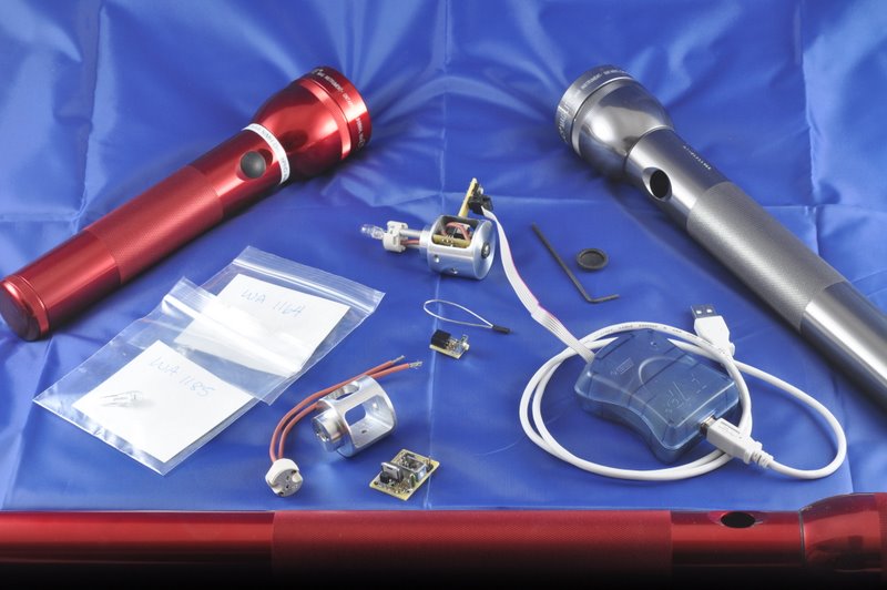
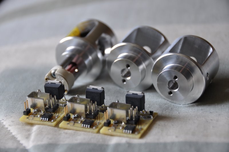
Thanks for that clear picture, Lux. I see more of the reason behind the testing and disassembly of socket candidates for Alan's sled.

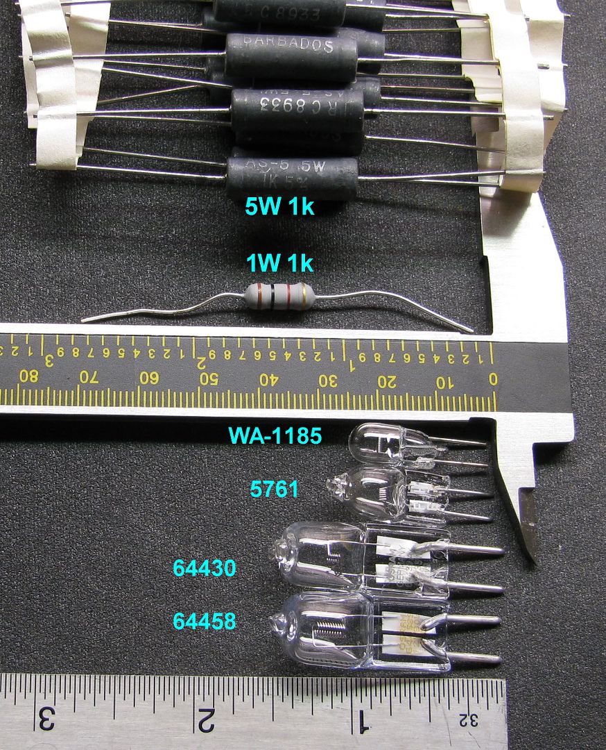
It looks like the 64430 (at least in that line-up) has an ideal filament for a real thrower. I don't have any experience with serious hotwires yet. How much does filament shape determine beam focus?
 

Alan B

Flashlight Enthusiast
Joined
Nov 19, 2007
Messages
1,963
Location
San Francisco Bay Area
Progress Report -

Today I worked on the SMD setup. I tested the setup on a Low Power 50 ohm RF Dummy Load which was interesting since it has parts on both sides and if you get the board too hot the parts on the bottom side might drop off while you are soldering the top side. I had no such problems with it.

So then I tackled one of the new Hybrid SMD Regulator boards. I finished assembling it and the two related boards an hour ago. Next is to test it. With a little luck this will be the one to go back to LuxLuthor. What battery/bulb do you want this one set for, Lux?????

Soldering under the microscope is really neat. I'm using 5x magnification and the working distance is about five inches (board to first lens), plenty of room to get in there. The soldering pencil has a tube that vacuums the soldering smoke so the microscope lens doesn't collect it.

I did find one minor problem in the PCB - the pads for the microprocessor are not quite right, they work but could be better spaced, so I can fix that before I get a large quantity of boards made.
 

CancerLad

Newly Enlightened
Joined
Sep 10, 2006
Messages
60
Alan, do you think it your switch would work with a sled made of plastic, like ABS or HDPE? You state that the regulator does not get hot in your faq, so do you think it needs to be metal for any heat conduction related reason?
 

Alan B

Flashlight Enthusiast
Joined
Nov 19, 2007
Messages
1,963
Location
San Francisco Bay Area
Alan, do you think it your switch would work with a sled made of plastic, like ABS or HDPE? You state that the regulator does not get hot in your faq, so do you think it needs to be metal for any heat conduction related reason?

I considered making them of plastic. Any heat problems are going to be from the bulb rather than the electronics. The metal sled is the ground current path, so using plastic would add some problems to solve there.
 

LuxLuthor

Flashaholic
Joined
Nov 5, 2005
Messages
10,654
Location
MS
What battery/bulb do you want this one set for, Lux?????

Alan, great progress! I'm not entirely clear what all changes you made, and how they affect the bulb voltage/current capability...but you can pretty much assume I have every combination of bulbs and batteries to test most anything your heart desires.

I am not sure if higher voltage and/or bulb amps and/or higher Vbat from Vbulb-rms type tests--more in hardware upgrade that needs to be stressed, or just software changes.
 

Alan B

Flashlight Enthusiast
Joined
Nov 19, 2007
Messages
1,963
Location
San Francisco Bay Area
The changes made to the SMD version are smaller parts and fewer holes in the PCB. The FET is the same, the large current traces were actually slightly increased, the fuse is the same. The calibration resistors are higher precision and stability. I'll have to take some photos after I 'finish' the PCB install - connect the socket, put in the ground screw, etc.

Just looking at it, now there is a lot of space and things look much less crowded. All the on-end resistors are gone, the microprocessor is smaller, etc.

I'm planning to put a KIU socket on this one. Perhaps we should test it at the high current end of the scale.
 

Alan B

Flashlight Enthusiast
Joined
Nov 19, 2007
Messages
1,963
Location
San Francisco Bay Area
The Hybrid/SMD first article has been fully assembled with Kiu socket. It passes ohm-meter tests. Next more testing and take some photos. It sure is a lot less crowded in there than the through-hole unit was. The insulation on the Kiu socket is also a bit easier to work with.
 

Alan B

Flashlight Enthusiast
Joined
Nov 19, 2007
Messages
1,963
Location
San Francisco Bay Area
The Hybrid/SMD unit has been bench tested and calibrated into a meter.

I tested the auto-shutoff at 1 minute. It worked. Not sure what happened there, I'll have to test at 10 minutes.

I adjusted the PCB layout to move the cpu pads a bit, they were not spaced quite right between the rows for this ic package.

More testing is planned. Lux, did you decide what battery and bulb is going to be your next test?
 

Alan B

Flashlight Enthusiast
Joined
Nov 19, 2007
Messages
1,963
Location
San Francisco Bay Area
Lux, whichever you think is more interesting. They all look fine to me. I can calibrate and program the regulator as soon as you select the values.

I soldered up another Hybrid board this evening. They're getting better and faster as I learn little tricks. It does take a steady hand, and that takes some practice, too.
 

Alan B

Flashlight Enthusiast
Joined
Nov 19, 2007
Messages
1,963
Location
San Francisco Bay Area
DSC_1305.JPG


New Hybrid SMD PHD-MD Hotwire Regulators, hot off the press.
 

Alan B

Flashlight Enthusiast
Joined
Nov 19, 2007
Messages
1,963
Location
San Francisco Bay Area

Alan B

Flashlight Enthusiast
Joined
Nov 19, 2007
Messages
1,963
Location
San Francisco Bay Area
Power supply ordered. 50V 3A. Won't run big bulbs but should be fine for calibration and testing above my present 18V PS.

I'll probably go ahead and use my existing supply to calibrate the test regulator, it should be close enough, rather than delay it another week.
 

Alan B

Flashlight Enthusiast
Joined
Nov 19, 2007
Messages
1,963
Location
San Francisco Bay Area
Let's do this one since some have gotten it from Modamag.

It uses Osram 64647 (default) 250W 24V 11.2A ...then overdriven.

Probably I'll use 9 x IMR 18650 to give charged 9 x 4.1V= 36.9V

Under 12A demand, will drop to 3.8V per cell (34V total)

So Regulated Bulb voltage set to 27.5V and shutoff at 3.2V/cell or 28.8V

I set up SN002 using a 19V power supply. I had to temporarily turn of the low voltage shutdown to calibrate it. It should be close:

#define VHI 27.5 // bulb high setting, in RMS volts
#define VLO 5.0 // bulb low setting, in RMS volts
#define VBATT 34.0 // nominal battery voltage
#define VBATLO 28.8 // min battery voltage
#define MAXONTIME 1 // limit ontime to N minutes after last input
#define V12S // 12S voltage range

I did notice the 1 minute shutoff kicking in, so it works at the 1 minute level. Never did find anything wrong with that code. I did not retest it at 10 minutes yet, but 1 minute seems like a better value for this power level.
 

LuxLuthor

Flashaholic
Joined
Nov 5, 2005
Messages
10,654
Location
MS
Yeah, my own linear PS is 30V/20A, so I can't do the destructive tests on the higher voltage bulbs beyond this one....and thank God it flashed at 29.6V !!!
 

Latest posts

Top