Arc LS (First Run) Board - Stock or not ? [NOW w/ CREE !!]

bombelman

Flashlight Enthusiast
Joined
Aug 26, 2005
Messages
1,751
My happy friend with his Arc LS First Run aka Grey Kit.
IMG_5205.JPG


After a heated discussion, he gave in to me operating on his Arc.
IMG_5215c.jpg

Sad Scene...
IMG_5216c.jpg


You can see the board has a tiny switch...
IMG_5220.JPG


The board is very thin and sticks on a round aluminum disc.
What I really like about this concept is that this sinks has wide
shoulders to sit on in the Arc head itself... Good for heatsinking...
IMG_5227c.jpg


The Pos [+] wire comes from a hole in the sink and is connected to
a piece of copper, which is insulated from the sink by glue.
IMG_5224.JPG


I performed tests to see current-draw from the battery.
The 2 switch positions are described as A and B.
The 3.0v cell it a Toshiba CR2 Lithium cell.
The 3.9v cell it an AW R123 I charged a few nights ago.

Switch on A - 3.0v - current draw: 0.33A.
Switch on A - 3.9v - current draw: 0.29A.

Switch on B - 3.0v - current draw: 0.65A.
Switch on B - 3.9v - current draw: 0.44A.

Not sure where these boards came from,
I think thet are an aftermarket part.
Someone suggested CPF-member Moses or maybe his brother ?
If anyone can confirm this, it would be great.

Does anyone know how resitors can be swapped for different
drive-currents ? Stock emitter drive-currents of this board
should be 200/400mAh to the LED.

Maybe somethine like 350/700mAh would be nice for driving a
a Cree or SSC emitter stock and overdriven.

And another thing, if you have any of these or other Arc boards
you would like to part with, please drop me a PM...

Cheers !!
 
Last edited:
Re: Arc LS (First Run) Board - Stock or non-stock ?

George, can you post a macro pic of the board (large enough to be able to read the componet marks).

Paul
 
Re: Arc LS (First Run) Board - Stock or non-stock ?

Now that I have seen the Macro shot, I see that what I had posted here is was incorrect.
 
Last edited:
Re: Arc LS (First Run) Board - Stock or non-stock ?

Thanks for chimin' in, Paul...

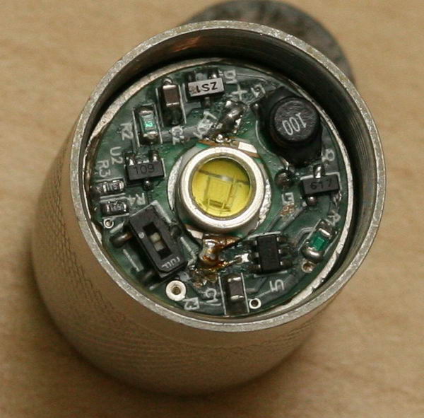
Here ya go:
IMG_5255c.jpg

Don't own any macro-lenses, so this is a crop from a 12MP pic...

Cheers !

EDIT: notice the [neg] of the led, next to the switch,
has a wire going to the chip, going to the middle of 3 pins.
It's the chip where it sais U1 (upside-down)...
What does this wire do ?
 
Last edited:
Re: Arc LS (First Run) Board - Stock or non-stock ?

Need I say any more ??? :lolsign:
IMG_5264c.jpg

BTW, even on low, this thing is a SCREAMER !!!

BTW, not sure if you've notice from the above pic, there are 2 brown
resistors at 2'o clock which are stacked on top of eachother :)
IMG_5266c.jpg
 
I still can't make out all the components, however, there are at least a couple from Zetex. Considering the date these were made, it's probably a boost converter. What's the top mark on U1?

You can measure the current to the emitter by checking the voltage drop across the sense resistor (R2 = 0.3ohms).

Interesting figures with your current draws - not what I would have expected. Which current setting did you use for your DMM?

Paul
 
U1 reads C420...

I retried current-draw form the battery and there were different readings, I will try again and repost also. Should current-draw be higher with a 3.0v or 3.6v cell ?
Only 1 current-setting, it says 10AMP and the readings read like 0.33 and such....


How do I measure voltage-drom on R2 ? Just put DMM on Volts and put on the resistor ?

Thanks man !
 
The current draw will depend on a couple of factors: Vf of the LED and the type of converter. Most of the boost type converters do into a direct drive mode if Vbatt exceeds the Vf of the LED at the set drive current. With Li-ions, the LED usually gets over-driven (think stock Q3 circuit).

The driver losses at that point would be the inductor DC resistance and the voltage drop across the Schottky diode (D1 marked ZS1).

U1 is a Zetex ZXSC420 boost converter. It may be using a current feedback scheme - I have not found U2 yet. It looks like someone has been monkeying with one of the boards in your pics - there looks to be a capacitor in the R3 slot in one pic.

Yes on measuring the drop on R2. You may need to use the mV scale. (I=V/R)

Paul
 
Last edited:
I'll try to decode what you just wrote when I get up later...

The zetex ZXSC420 says:
"1.65V to 8V supply range" and "Output currents up to 300mA".
How does this chance, since the board is a 200/400mA board ?
(Is this true btw ?)

Also, if it says "Over 85% typical efficiency", does that mean,
current drown from battery is 100/85 of current driven to LED ?

Electronics newbie here... :lolsign:

Thanks again for this wonderful education... ! :rock:
 
i remember these lights selling on ebay.

they were by the guy who sells the pierce m10.

he had gotten spare arc parts and added his own board with switch.

i think it was 200ma/400ma.

i had bought a couple of them, they were nice.
 
I remember these too. It looks exactly like the ones that were on ebay. I was bidding like a mad man and never won. The switch is a pretty cool option.
Cheers
 
OK, the part I thought was "60L" (U2) is actually "109" a Zetex ZXCT1009 a high side current monitor. It converts Vsense (the voltage drop across the sense resistor) to a current (Iout). (100mV -> 1mA, 1000mV -> 10mA).

Iout is fed through a resistor network (and switch) to provide a feedback voltage to the Zetex 420. The feedback voltage for the Zetex420 is 300mV - if the chip senses a lower voltage, it increases the drive. If lower, it decreases it.

If the settings of the board are actually 200/400mA, and Rsense is 0.3 ohms, then Vsense is 60/120mV and Iout is 0.6/1.2mA respectively.

I need better photos of R3, R4 and R1. It would also help to be able to better see the PCB traces. :)

It should be fairly easy once the switch and resistor configuration is known to supply some different values for different currents.

Cheers,

Paul
 
Chimo: "and Iout is 0.6/1.2mA respectively".
So are drive-currents to the led really 200/400 mA (or somehwere there) ?
As this circuit was designed for 3.0v, how will
a 3.6v Li-Ion affect drive-current ?

I don't own a macro lens but will take macro pics with macro camera.
Thanks again. Cheers !
 
George, the Iout I mentioned above is for the chip at U2 - it does not go to the LED. It provides the feedback to the chip at U1 so that U1 can provide more or less boost as required to maintain regulation.

What a Li-ion does is cause the current through the sense resistor to go up to the point that the feedback to the switcher IC keeps telling it to reduce boost to the point it stops boosting. The circuit then goes essentially direct drive through the inductor and sense resistor to the LED.


Paul
 
An additional note for the Zetex420. There are two feedback points it, Sense and Vfb.

In this case, R1 is the inductor current sense resistor and R2 is a high side sense resistor to provide feedback (through additional components) to the Vf pin.

Paul
 
Paul, since we're in 2007, what do you think of the design of the circuit and the components themselves ? (Think efficiency) Any current parts which would be compatible ?

The reason I ask is that I know from the stock Arc LS First Run boards are different, in a way that they ran (or still can run) a LuxI or even a LuxIII on an AA-cell, even if that AA-cell will not light up other lights...

What I'm thinking is to make it a Cree-light running from an AA-cell.

I'm at my sister's now and will take macro-pics of the other aftermarket
board and post them here also. Cheers !
 
Cool! I haven't read the whole thread here as I got too excited when I saw this - I've got one just like this too - yes Moses brother who I'm quite sure is also the guy who made the Pierce lights that come with two optics and are on closeout now. I always wondered if I could put a Cree on their. This board is supposed to be 400ma/1000ma depending on switch setting.
 
If you look closely at the components from the 1st run boards you will notice two parallel circuits. These circuits are essentially the same as the ArcAAA circuit.

They are boost only and that's why they will draw the battery down so low (they are made for a lower battery voltage).

The one you have there has real regulation. You would have to do a power-in/power-out calculation for a sweep of input voltages to get a good idea of power.

Just a real swag, but efficiency is likely in the low 80s (it will vary depending on the input voltage and the switch setting). There are more efficient components, but if that works and fits....

It likeky wouldn't be worth the trouble upgrading any components.

From what I can see of the design so far it is sound. The feedback scheme is similar to what dat2zip uses on some of his boards (high side sense).

Paul

bombelman said:
Paul, since we're in 2007, what do you think of the design of the circuit and the components themselves ? (Think efficiency) Any current parts which would be compatible ?

The reason I ask is that I know from the stock Arc LS First Run boards are different, in a way that they ran (or still can run) a LuxI or even a LuxIII on an AA-cell, even if that AA-cell will not light up other lights...

What I'm thinking is to make it a Cree-light running from an AA-cell.

I'm at my sister's now and will take macro-pics of the other aftermarket
board and post them here also. Cheers !
 
Top