wquiles
Flashaholic
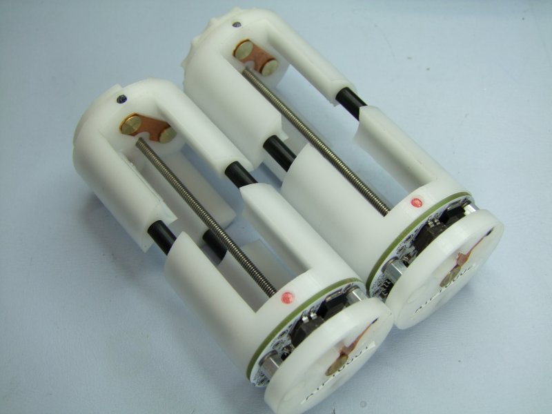
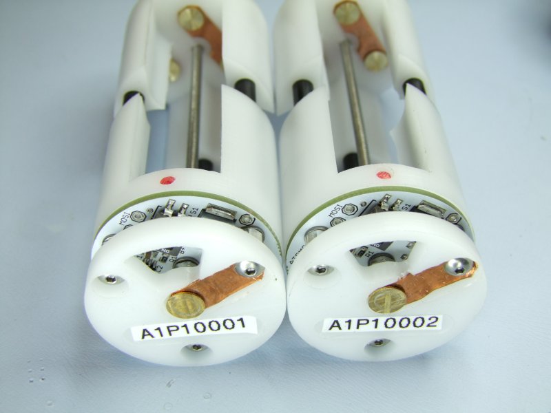
The PhD-M6 battery pack is a custom pack for the Sure Fire M6, and it is composed of a custom battery pack designed and built by Eric (mdocod), and a custom PWB/driver and firmware done by me. Eric recently finished a great post showing how he creates the PhD-M6 custom battery pack, and this post shows what happens after Eric sends me the finished battery carrier to become the complete PhD-M6 pack.
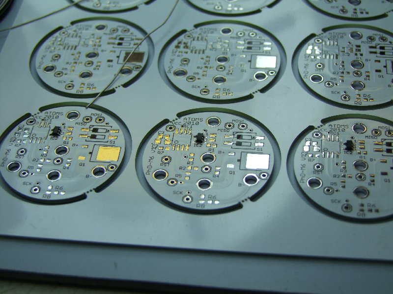
Here is the panel with the bare PhD-M6 production boards that I designed (again, kudos to Alan, Jimmy, and George for their help!):

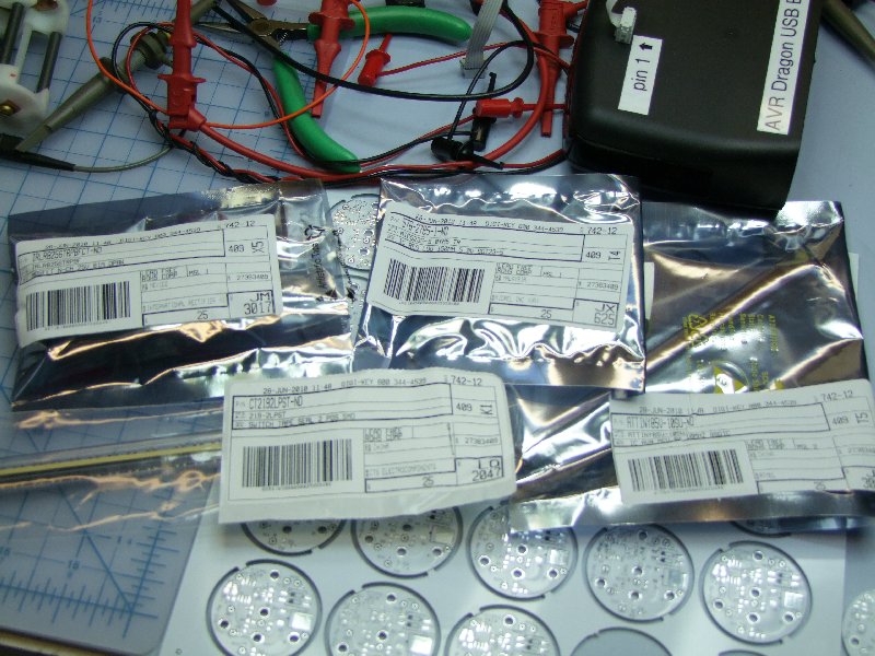
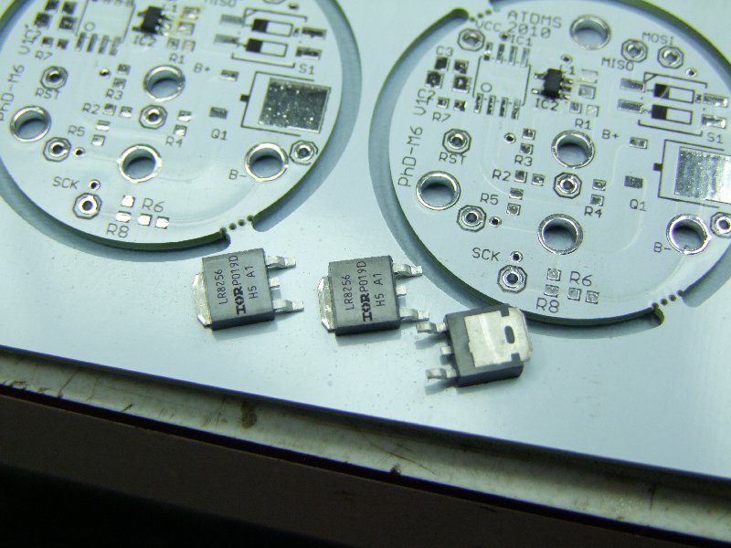
These are the parts I got from Digikey for this board:
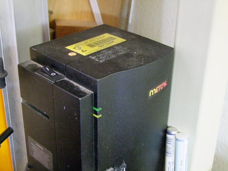
I am using a Metcal MX-500 with the stylus wand:
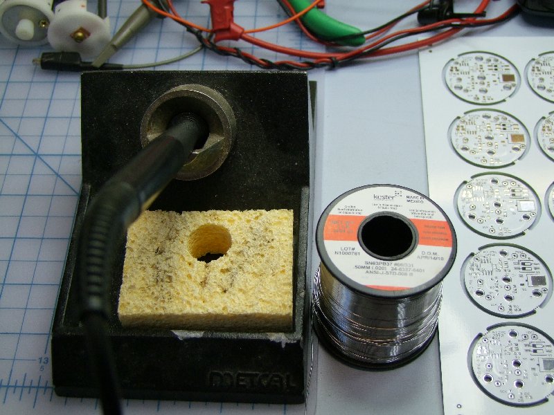
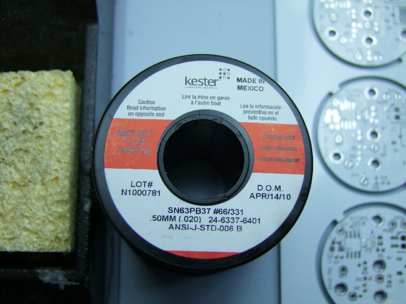
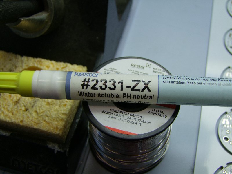
For solder I am using this outstanding Kester solder and flux pen:
I will be updating the order as I build more and more of these, but first I start with the 5V Voltage regulator:

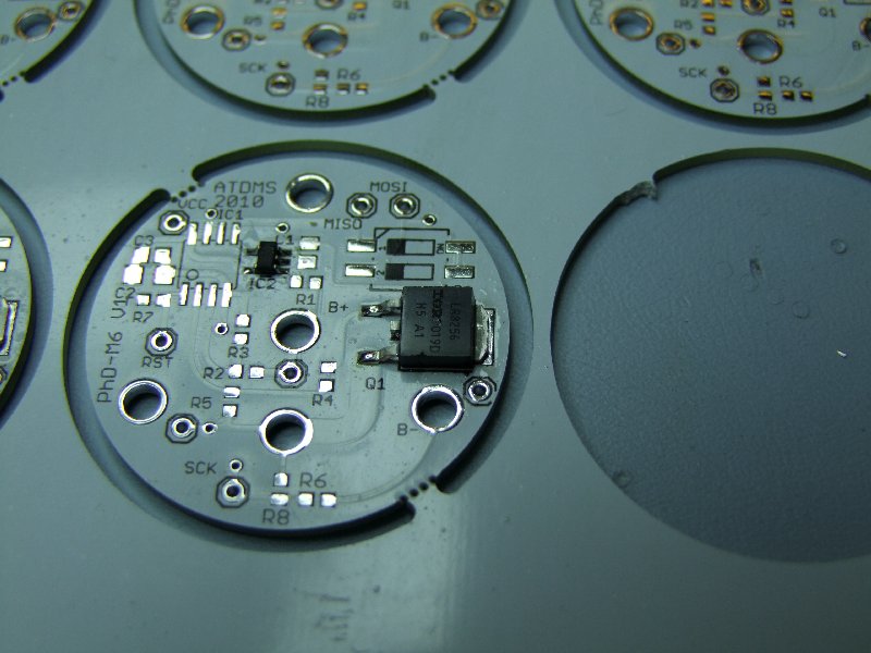
then the MOSFET:
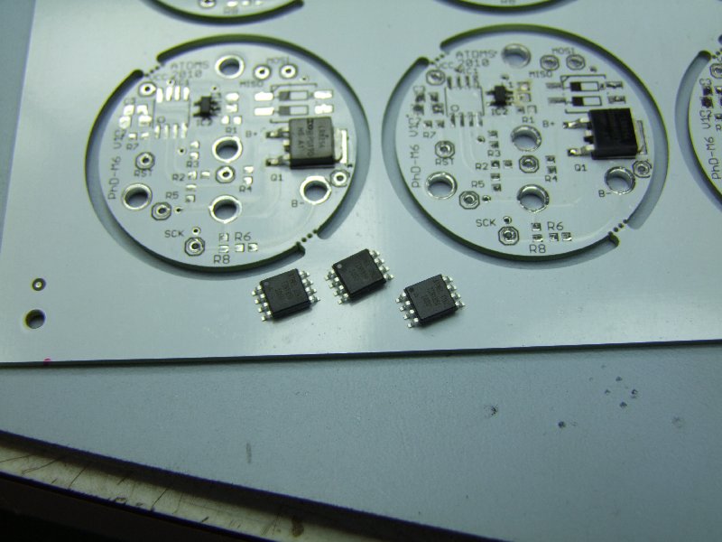
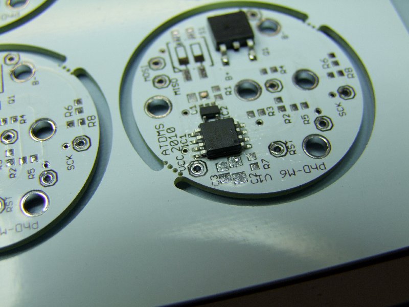
then the Tiny85:
then the DIP switch:

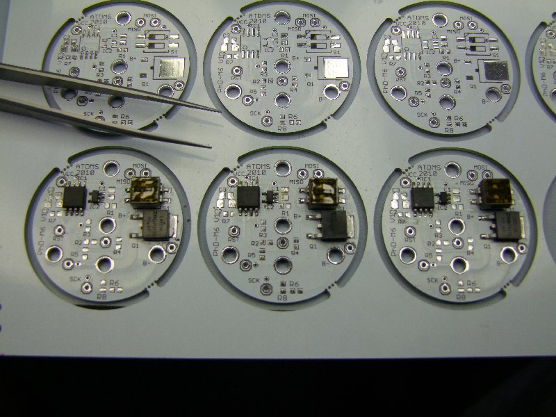
I then do the resistors - yes, they are that small (0805 to be exact):
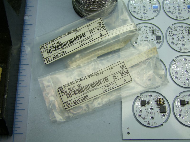
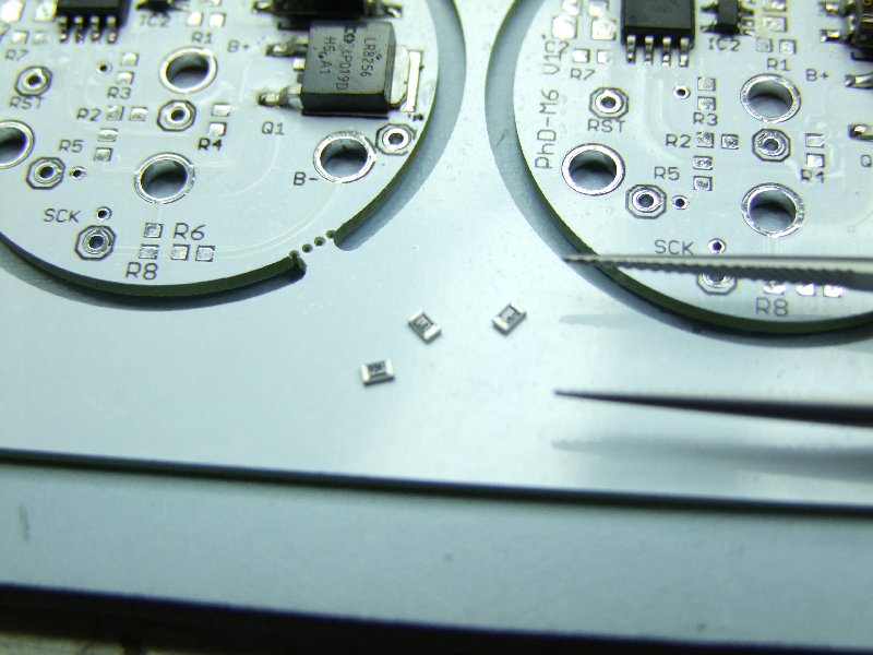

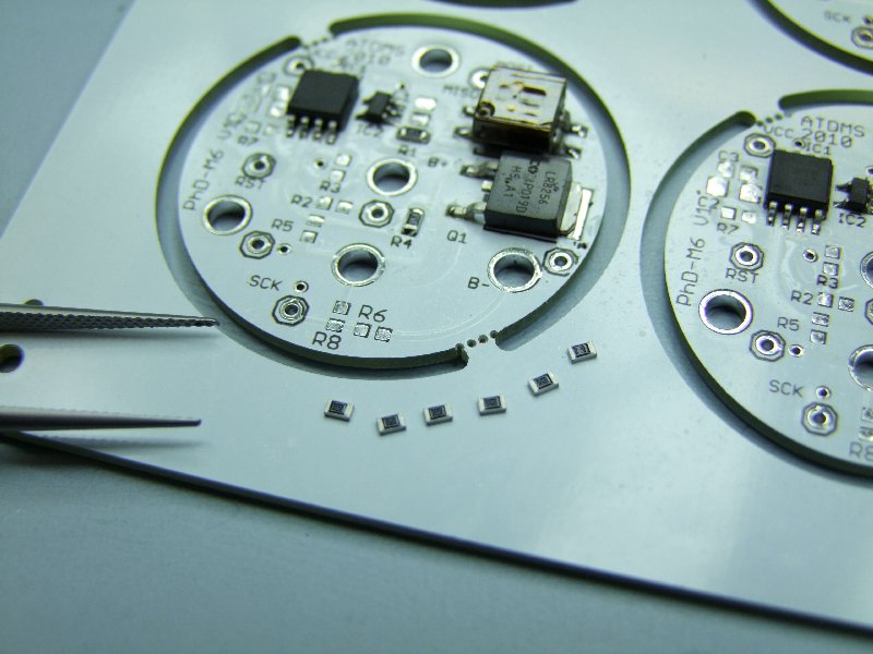
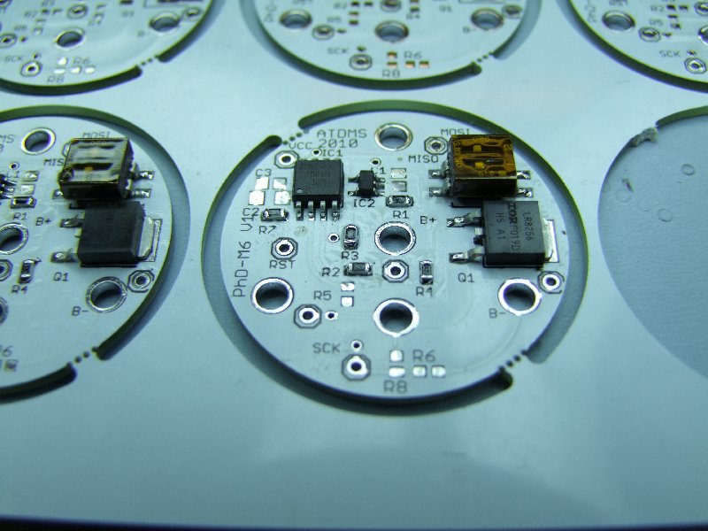
more resistors:
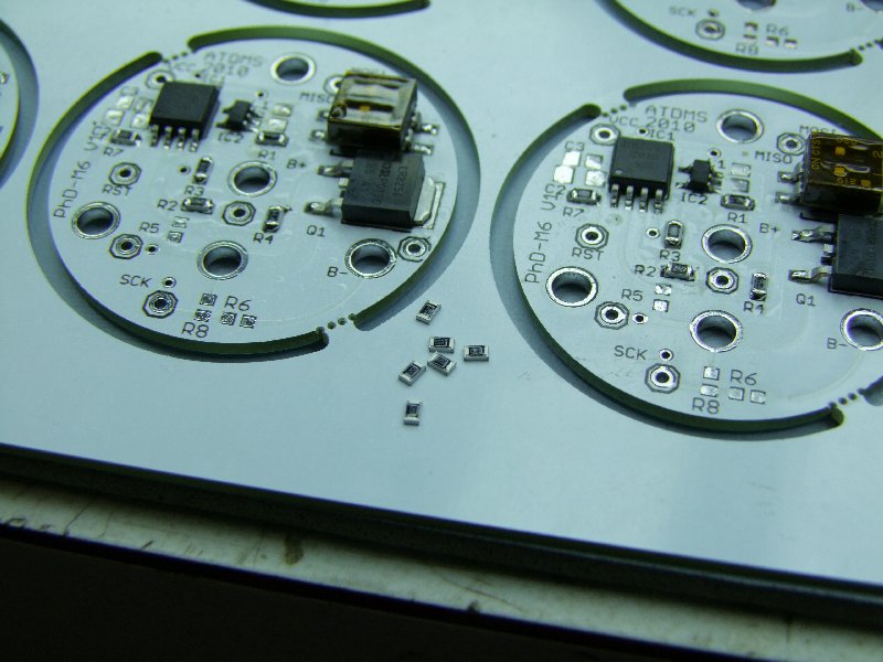
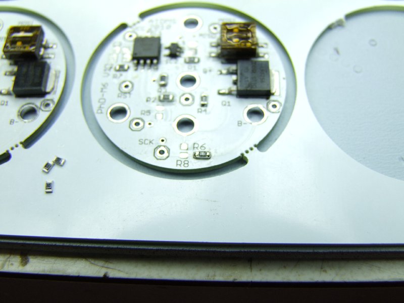
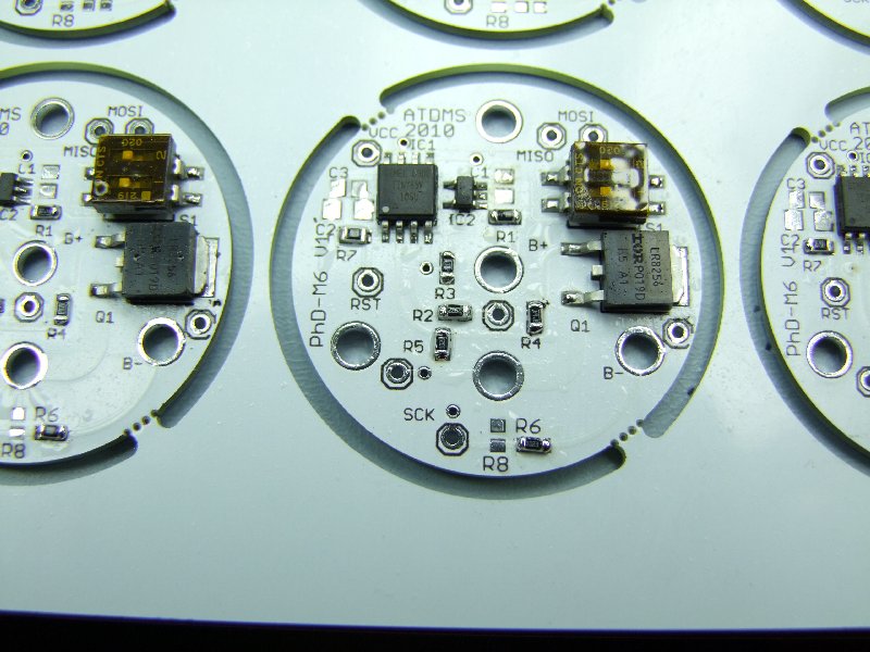
Then I move into the capacitors:
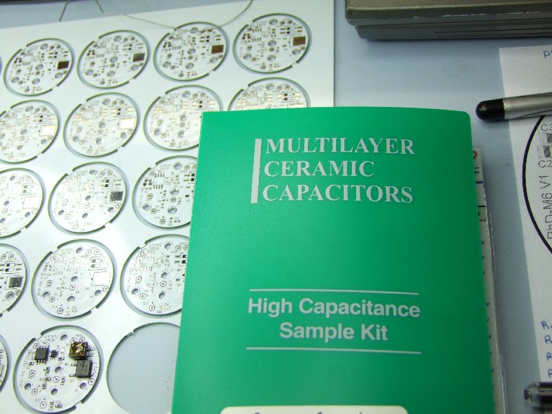
Trivia - which capacitor has a higher value? :devil:
(the small cap is a 1uF - the large one is a 100uF!):
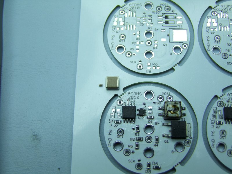
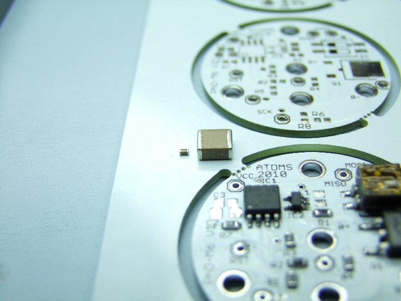
But we don't need anything that big. These are the sizes I will be using:
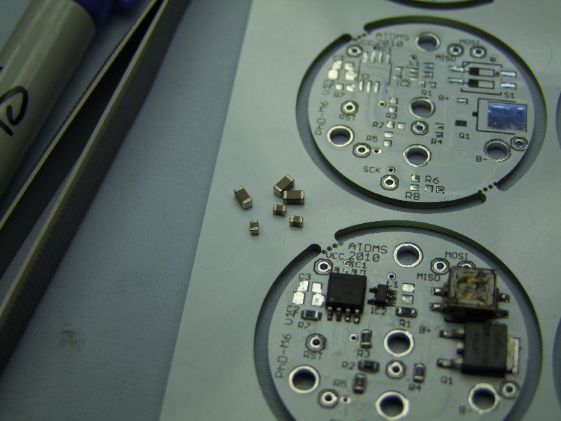
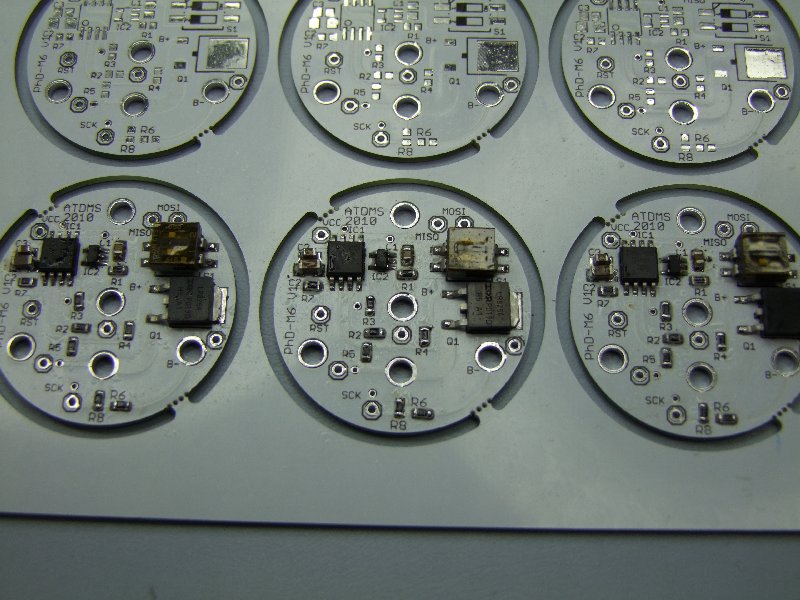
As you can see in the pictures, the board has been progressively getting more and more dirty with the flux. Since this water-soluble flux is somewhat corrosive, it MUST be cleaned. First I separate the finished boards from the panel:
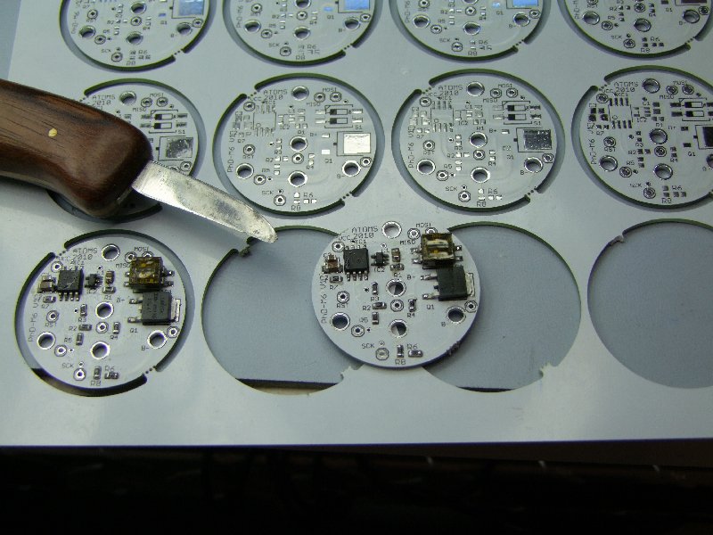
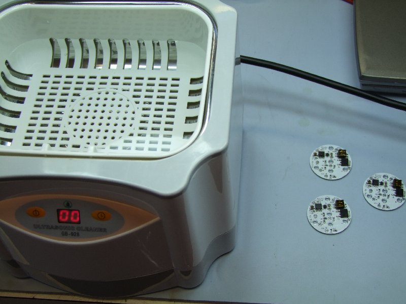
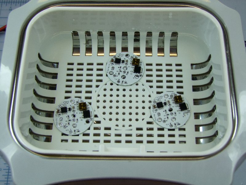
Then to clean the boards in an ultrasonic water cleaner for 5 minutes:
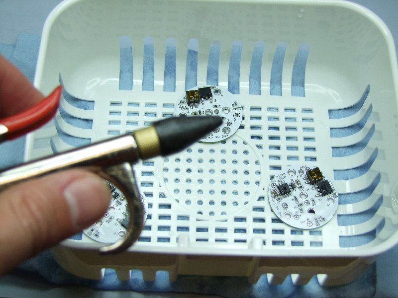
Once they are ready, they need to be dried off:

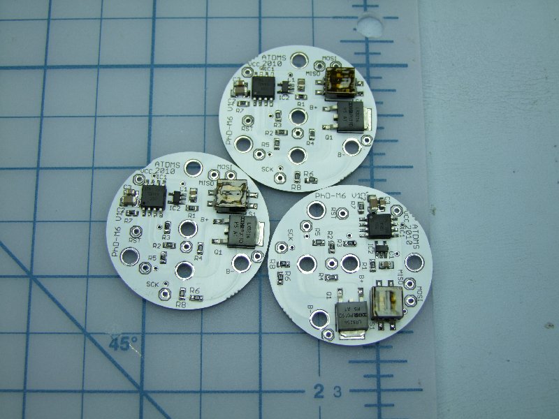
Nice and clean:
I first remove the cover that protects the switches from the "bath":
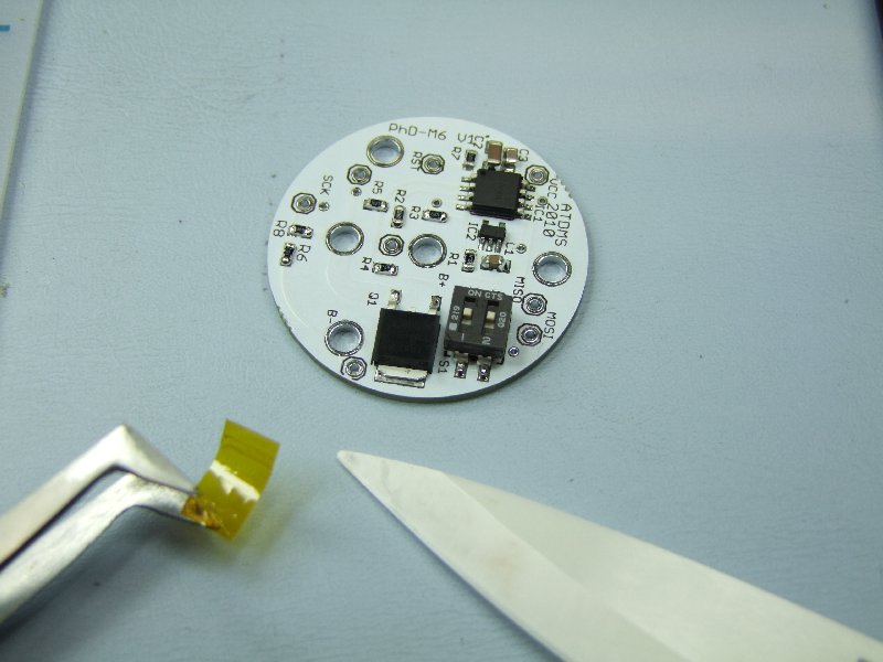
Now they are ready to be tested:
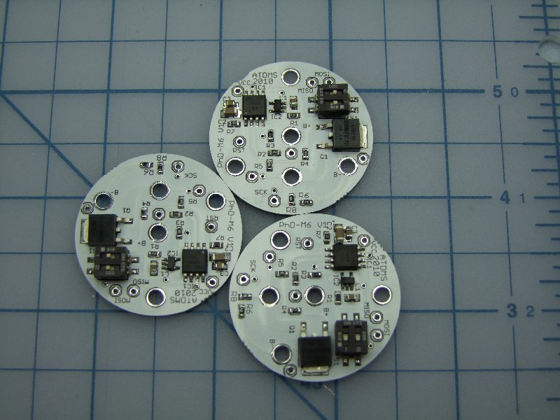
I first check them in my special fixture. Here I am using low current protected cells in case I have a short/problem. Assuming things are well, this fixture allows me to test the 5V regulator and verify that the AVR Dragon tool can read/talk to the Tiny85:

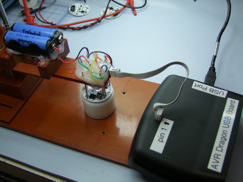
Once I can read the signature, I do the initial programming, set the fuses and lockout options, and then I am ready for the next step:
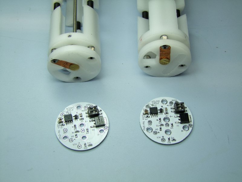
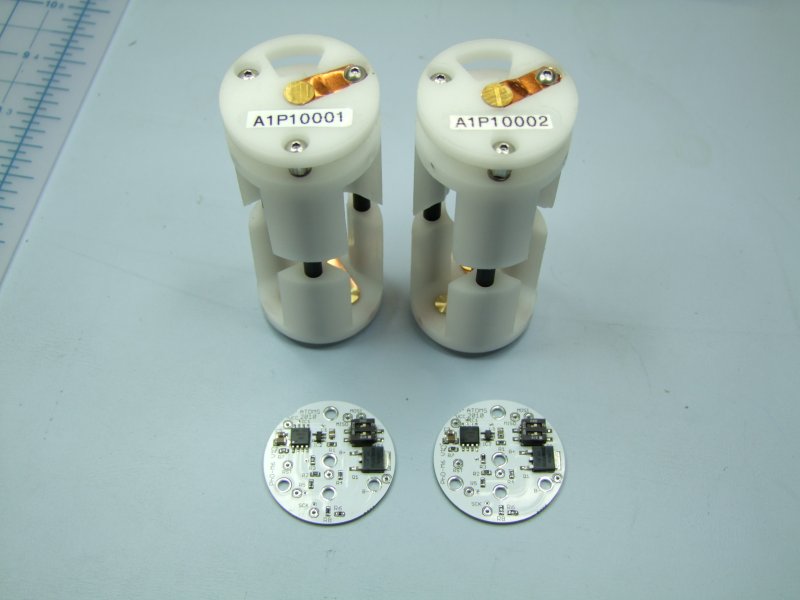
Here are the two prototype packs that are going out for field testing. One for Eric, and one for forum member leukos:
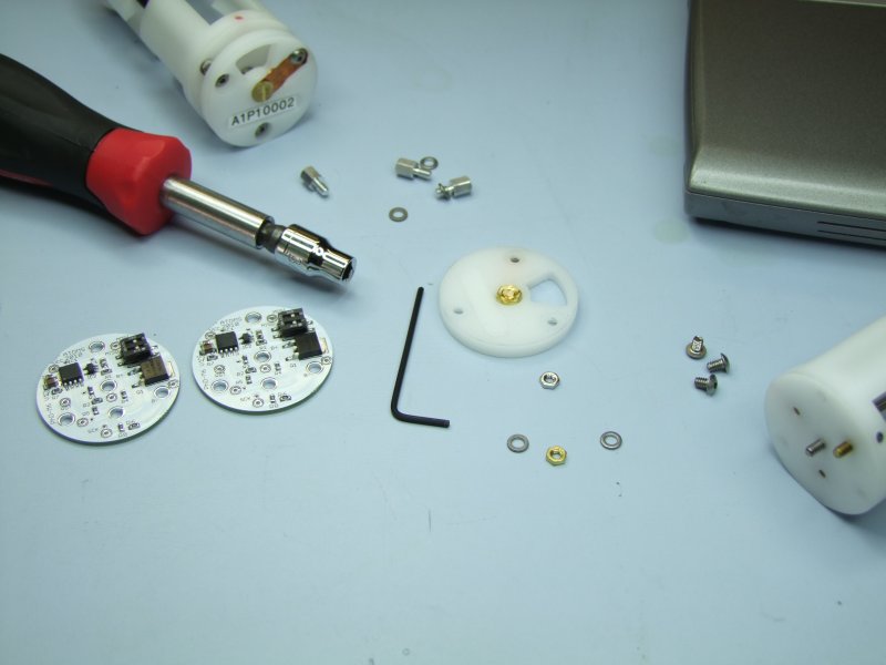
I disassemble the top of Eric's battery carrier:
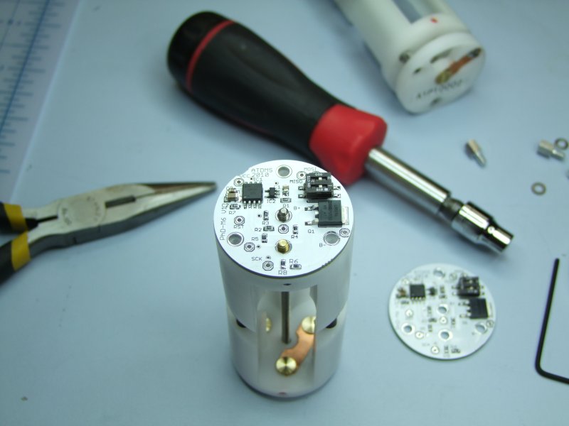
place the board and center:
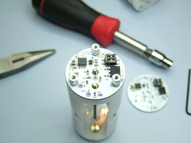
install the outer screws/stand-offs:
then the center (Battery plus) and lower center (Battery minus) connections:

I then install the protected 17670 cells - NOTE that Eric clearly marks the Pos and Neg side for each of the 3 cells. The pack might be damaged if the cells are connected backwards!:

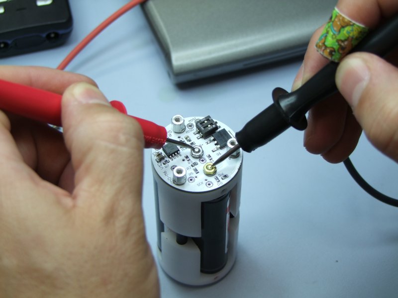
I first check the pack's voltage (note I am using my Son's Scooy-Doo band-aid for a boo-boo in my finger!) :
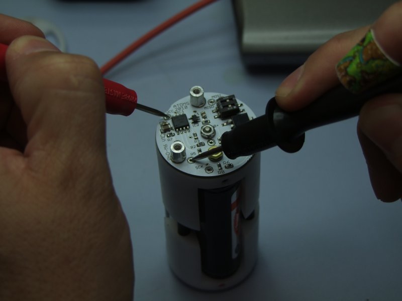
then I check the regulated DC voltage at the Tiny85:
Once the pack is running good, I then proceed to test what are the outputs, so that I can calibrate each pack with a small correction factor. This part is slow, but makes sure each regulator is as close as possible to the target voltages as possible.
Please note two things:
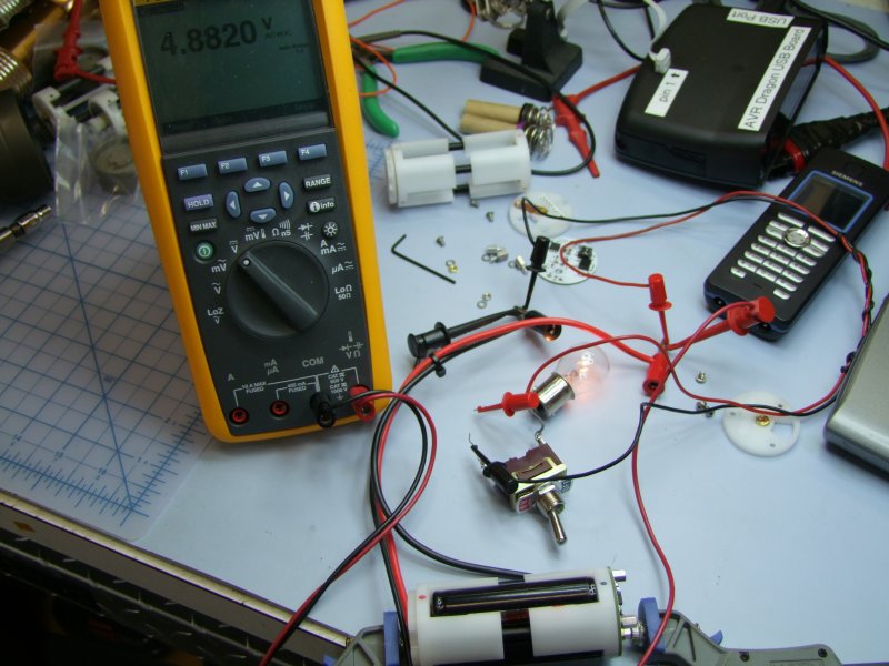
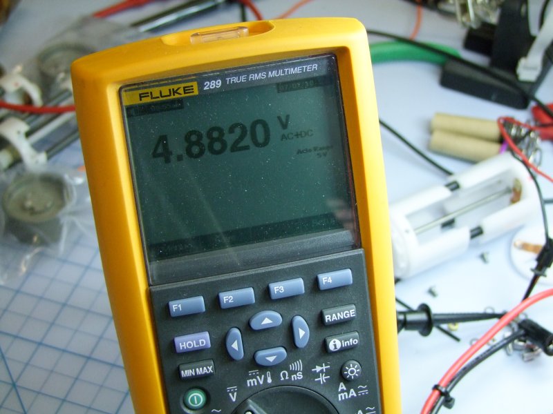
1) You can't measure the regulated output into a bulb with a normal True-RMS voltage meter. You need a special meter that can measure both the AC and DC components of the PWM signal, as True RMS meters only measure accurately at a duty cycle of 50%. Since the regulator varies the duty cycle to compensate for the battery as it drains, only a meter with AC+DC capability will give you the correct value.
2) The pack goes to sleep if there is no bulb across the pack. If you put a bulb across the pack, then the regulator will wake up and start regulating, which would then allow you to use your AC+DC meter to measure the actual RMS Voltage.
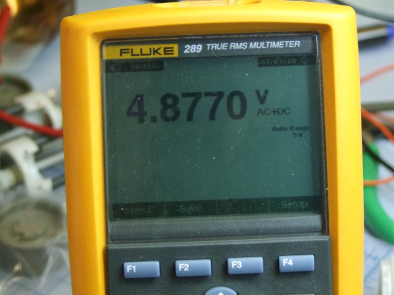
First test the 4.9 volt output - note that the output does vary a bit between photos as the regulator is constantly adjusting/compensating as the battery drains:
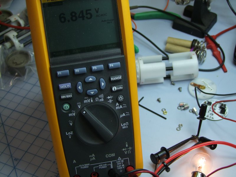
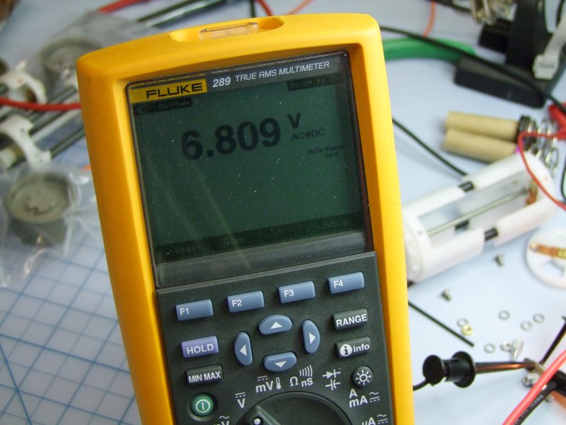
Then the 6.8 volt output:
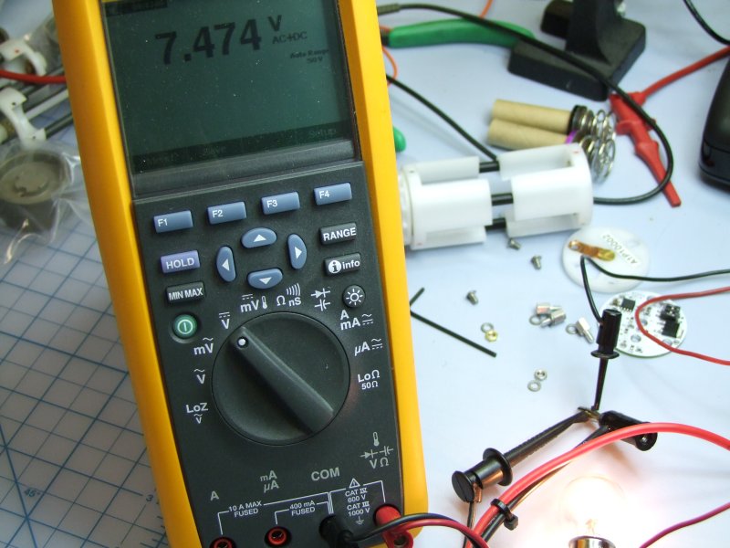
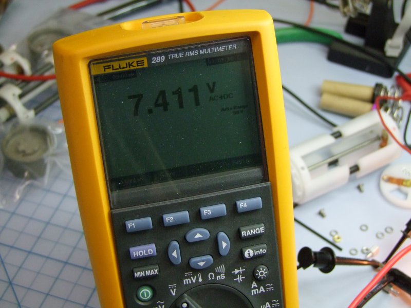
Then the 7.4 volt output:
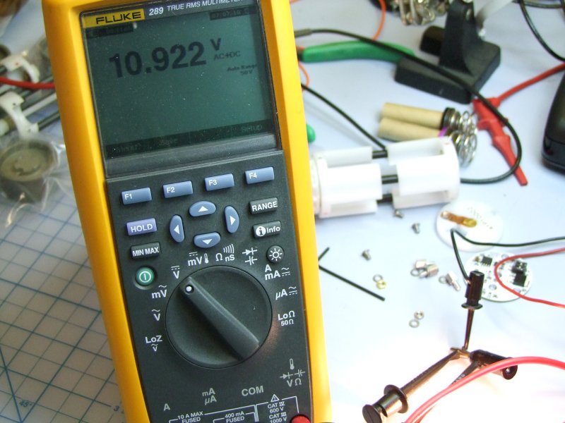
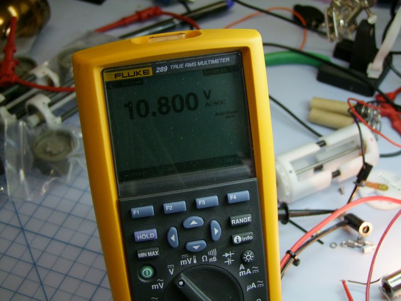
and the 10.8 volt output:
Then compare to the target:

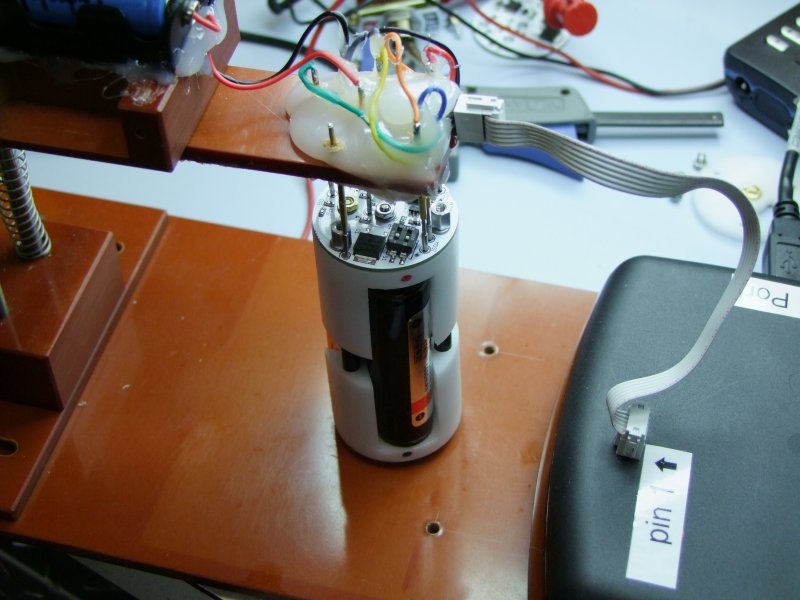
Calculate an average compensation factor, and re-program the pack:
After calibration, these are the new outputs (4.9 volt target):
6.8 volt target:
7.4 volt target:
and 10.8 volt target:
Here is the completed and calibrated PhD-M6 pack:
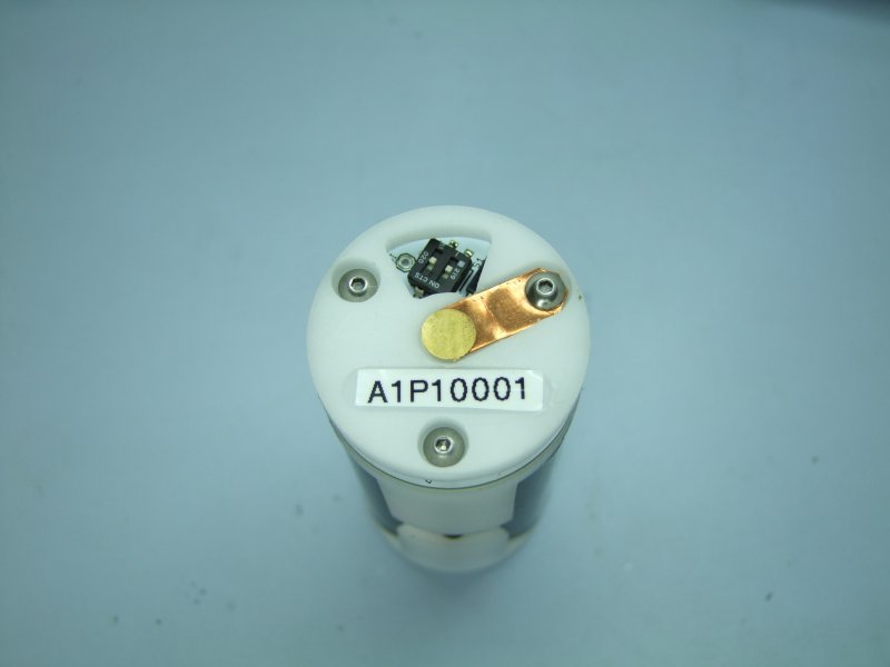
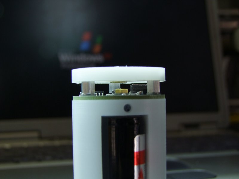
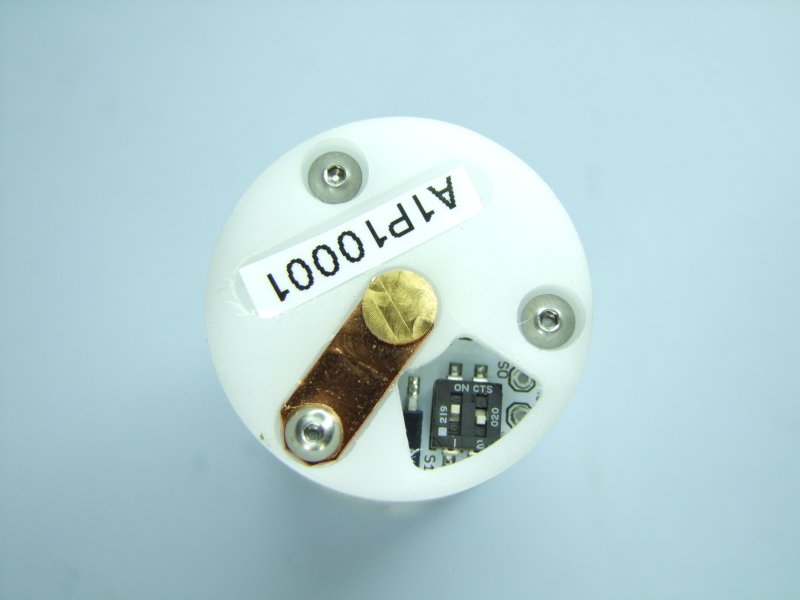
I then set the DIP switch to HIGH-LOW, to select level 3, 7.4 volts, since I am testing with the N2 in my own M6:
Insert pack into M6:
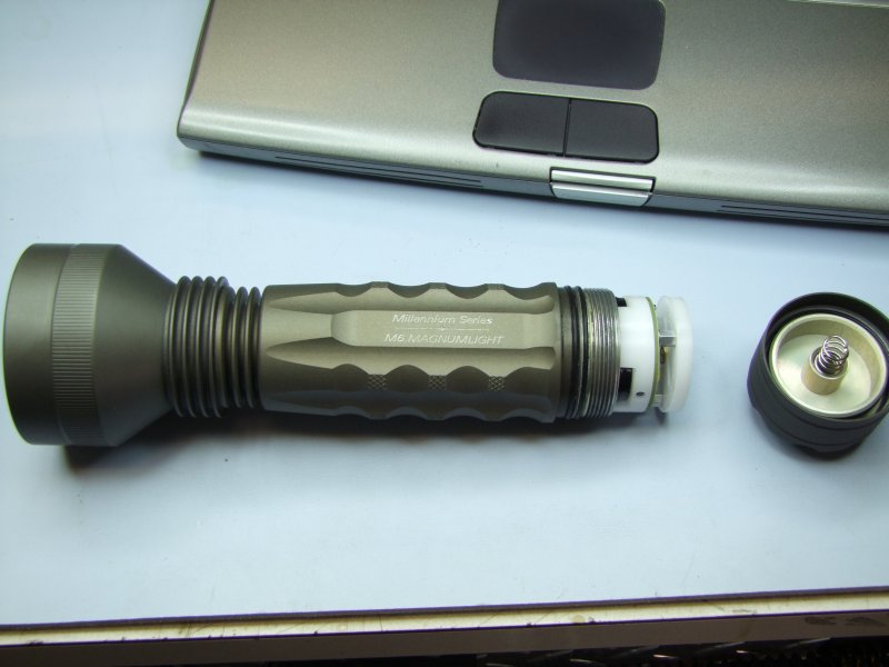
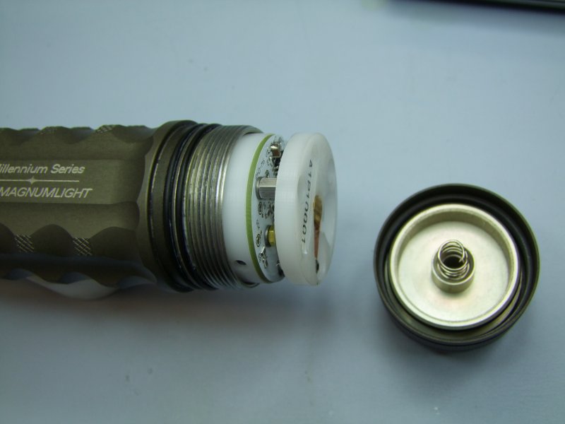
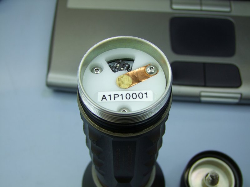
and voila! - a 12 volt battery pack safely driving an N2 at a regulated 7.4 volts RMS:
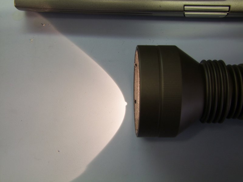
I then finished the second pack:
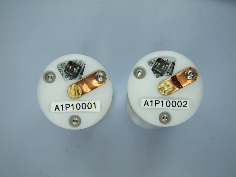
That is it for now - thanks for watching
Here is the panel with the bare PhD-M6 production boards that I designed (again, kudos to Alan, Jimmy, and George for their help!):
These are the parts I got from Digikey for this board:
I am using a Metcal MX-500 with the stylus wand:
For solder I am using this outstanding Kester solder and flux pen:
I will be updating the order as I build more and more of these, but first I start with the 5V Voltage regulator:
then the MOSFET:
then the Tiny85:
then the DIP switch:
I then do the resistors - yes, they are that small (0805 to be exact):
more resistors:
Then I move into the capacitors:
Trivia - which capacitor has a higher value? :devil:
(the small cap is a 1uF - the large one is a 100uF!):
But we don't need anything that big. These are the sizes I will be using:
As you can see in the pictures, the board has been progressively getting more and more dirty with the flux. Since this water-soluble flux is somewhat corrosive, it MUST be cleaned. First I separate the finished boards from the panel:
Then to clean the boards in an ultrasonic water cleaner for 5 minutes:
Once they are ready, they need to be dried off:
Nice and clean:
I first remove the cover that protects the switches from the "bath":
Now they are ready to be tested:
I first check them in my special fixture. Here I am using low current protected cells in case I have a short/problem. Assuming things are well, this fixture allows me to test the 5V regulator and verify that the AVR Dragon tool can read/talk to the Tiny85:
Once I can read the signature, I do the initial programming, set the fuses and lockout options, and then I am ready for the next step:
Here are the two prototype packs that are going out for field testing. One for Eric, and one for forum member leukos:
I disassemble the top of Eric's battery carrier:
place the board and center:
install the outer screws/stand-offs:
then the center (Battery plus) and lower center (Battery minus) connections:
I then install the protected 17670 cells - NOTE that Eric clearly marks the Pos and Neg side for each of the 3 cells. The pack might be damaged if the cells are connected backwards!:
I first check the pack's voltage (note I am using my Son's Scooy-Doo band-aid for a boo-boo in my finger!) :
then I check the regulated DC voltage at the Tiny85:
Once the pack is running good, I then proceed to test what are the outputs, so that I can calibrate each pack with a small correction factor. This part is slow, but makes sure each regulator is as close as possible to the target voltages as possible.
Please note two things:
1) You can't measure the regulated output into a bulb with a normal True-RMS voltage meter. You need a special meter that can measure both the AC and DC components of the PWM signal, as True RMS meters only measure accurately at a duty cycle of 50%. Since the regulator varies the duty cycle to compensate for the battery as it drains, only a meter with AC+DC capability will give you the correct value.
2) The pack goes to sleep if there is no bulb across the pack. If you put a bulb across the pack, then the regulator will wake up and start regulating, which would then allow you to use your AC+DC meter to measure the actual RMS Voltage.
First test the 4.9 volt output - note that the output does vary a bit between photos as the regulator is constantly adjusting/compensating as the battery drains:
Then the 6.8 volt output:
Then the 7.4 volt output:
and the 10.8 volt output:
Then compare to the target:
Calculate an average compensation factor, and re-program the pack:
After calibration, these are the new outputs (4.9 volt target):
6.8 volt target:
7.4 volt target:
and 10.8 volt target:
Here is the completed and calibrated PhD-M6 pack:
I then set the DIP switch to HIGH-LOW, to select level 3, 7.4 volts, since I am testing with the N2 in my own M6:
Insert pack into M6:
and voila! - a 12 volt battery pack safely driving an N2 at a regulated 7.4 volts RMS:
I then finished the second pack:
That is it for now - thanks for watching


