In the past I've been experimenting with LED driver circuits that draw the maximum power from a hub dynamo and feed this into some LEDs.
Here's a power vs speed graph that compares different configurations (3, 4 and 6 LEDs) with my latest driver circuit:
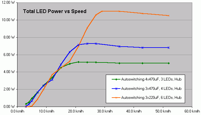
The driver circuit that can do this has been presented here and it's now confirmed that this same circuit can handle 3..6 LED systems as well as hub and bottle dynamos. Just the component values have to be adapted.
Now before I start work on a PCB, I ask around if there are people who want one and if it should be made in a certain way.
It will be an unpopulated PCB, I will not go into having modules manufactured.
So far I have discussed the project with ktronik and we said that it would have to fit into a steerer tube. So the PCB would be 1" wide but rather long, rectangular, not round.
The circuit requires 4 to 5 larger capacitors (in case of a hub dynamo, they can be bigger than the rest of the circuit) and these will not be put on the PCB but connected by wires. This way the PCB can remain small and the capacitors can be located where there is space. The PCB is estimated to take an area of around 16 sq cm (2.5 sq inch) without the external capacitors.
I wonder if the project should be done in traditional through-hole technology or rather SMT. While SMT can reduce the size and avoids the need to drill holes in the PCB, the components are more difficult to find and to handle for the hobbyist. Any opinion on this ?
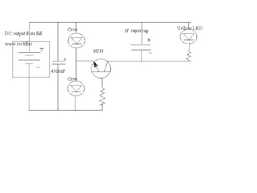
The circuit does not contain any stand light / battery / supercap / charger features. It neither contains a tail light driver / controller (but no problem connecting a readily made one across the main LEDs). Who considers these features essential ?
I intend to make the wire connection to the PCB by large solder pads. I consider this smaller and less prone to corrosion than any clamp or connector. What do you think ?
An overvoltage crowbar would have to be added to prevent damage to circuit and LEDs in case that the LEDs disconnect. I also plan on adding a strain relief for the connecting cables. These things will add length to the PCB but are needed when the driver circuit is not located inside the lamp cabinet. Maybe I should put them near the end of the PC so they can be cut away ?
Let me hear what you think.
Martin
Here's a power vs speed graph that compares different configurations (3, 4 and 6 LEDs) with my latest driver circuit:
The driver circuit that can do this has been presented here and it's now confirmed that this same circuit can handle 3..6 LED systems as well as hub and bottle dynamos. Just the component values have to be adapted.
Now before I start work on a PCB, I ask around if there are people who want one and if it should be made in a certain way.
It will be an unpopulated PCB, I will not go into having modules manufactured.
So far I have discussed the project with ktronik and we said that it would have to fit into a steerer tube. So the PCB would be 1" wide but rather long, rectangular, not round.
The circuit requires 4 to 5 larger capacitors (in case of a hub dynamo, they can be bigger than the rest of the circuit) and these will not be put on the PCB but connected by wires. This way the PCB can remain small and the capacitors can be located where there is space. The PCB is estimated to take an area of around 16 sq cm (2.5 sq inch) without the external capacitors.
I wonder if the project should be done in traditional through-hole technology or rather SMT. While SMT can reduce the size and avoids the need to drill holes in the PCB, the components are more difficult to find and to handle for the hobbyist. Any opinion on this ?
The circuit does not contain any stand light / battery / supercap / charger features. It neither contains a tail light driver / controller (but no problem connecting a readily made one across the main LEDs). Who considers these features essential ?
I intend to make the wire connection to the PCB by large solder pads. I consider this smaller and less prone to corrosion than any clamp or connector. What do you think ?
An overvoltage crowbar would have to be added to prevent damage to circuit and LEDs in case that the LEDs disconnect. I also plan on adding a strain relief for the connecting cables. These things will add length to the PCB but are needed when the driver circuit is not located inside the lamp cabinet. Maybe I should put them near the end of the PC so they can be cut away ?
Let me hear what you think.
Martin
Last edited: