Joule Thief just will not work!

twosouls2gether

Newly Enlightened
Joined
Oct 13, 2007
Messages
46
Hello everyone, it's been a while since I got distracted by life but back into flashlights again. I've been trying to build a little joule thief but it just won't work. Is there some secret I'm missing? I'm just using the basic resistor, inductor, transistor, led circuit, such as http://cappels.org/dproj/ledpage/leddrv.htm or http://www.bigclive.com/joule.htm. I have a few toroid inductors that I have wound myself with 30 AWG wire as well as 26 AWG I believe. I've tried more and less turns on the inductor. At first I got a very very very faint glow using a green led on a breadboard but after messing around with it I can't even get that back. I've tried different transistors that I have lying around such as 2N2222, BC558, BC547 and BC546's. I had to hook up a bypass capacitor across the 1k resistor to jump start it once as someone said on one of the webpages, however nothing after that initial attempt. I have even soldered it all together in a clump as someone on a youtube video commented on the parasitic capacitance causing it not to oscillate. It seems like such as simple circuit but it seems they are always the ones that will not work for me, go figure.

Anyone built one? Certain windings needed? Technique? Only one particular transistor that will work? Do I need to use a white LED since my white ones seem to have run off a hid on me. During one breadboard attempt the green led would light up nicely if I dragged the coil leg across the LED leg created noise or some such thing. I will have to dig out my oscilliscope but I have to wait until tomorrow sometime and it's just driving me nuts. What is the critical component/step I'm missing? Any help is appreciated and if I'm missing some info please ask.
 
I built this circuit a few years ago, and it worked OK with a 2N2222 transistor. One thing to watch out for is the winding direction of the inductor, both halves of the winding have to be wound in the same direction.
If you wind half of it, to the center tap, then accidentally turn the coil around and wind the 2nd half in the opposite direction, the two halves buck one another and the circuit will not work. Sooo, I'd strip the wire off your inductor, and mark it somehow to make sure that you wind both halves in the same direction.

Also make sure that the transistor is wired correctly, it's easy to get emitter and collector reversed...depending on whether you're looking at the top or bottom of the transistor.
 
Last edited:
Honestly I'd need to use the scope and go node by node comparing what is happening with the schematic until I understood what was going on. But, one thing I noticed on the schematic (I viewed, maybe not the one you used) is that the transformer connections were drawn funny and seemed prone to wiring error. It labeled the drawn wires A-B, B-A (instead of A-B, A-B I'd expect) and it seemed easy to misread and wire it backwards....

Might be worth a quick double-check. Good luck.
 
I built this circuit a few years ago, and it worked OK with a 2N2222 transistor. One thing to watch out for is the winding direction of the inductor, both halves of the winding have to be wound in the same direction.
If you wind half of it, to the center tap, then accidentally turn the coil around and wind the 2nd half in the opposite direction, the two halves buck one another and the circuit will not work. Sooo, I'd strip the wire off your inductor, and mark it somehow to make sure that you wind both halves in the same direction.

Also make sure that the transistor is wired correctly, it's easy to get emitter and collector reversed...depending on whether you're looking at the top or bottom of the transistor.

Well I have wound a few coils by folding the wire in half and then looping it 20 or so times like quite a few website suggested. Hmmm... perhaps that's where I'm going wrong? I have wound a few too were I wind a single layer on, pull out the center tap and keep winding but I think I may be winding the wrong way. I saw on one site where the guy said to not accidently twist your wires when you are winding as that is the biggest mistake... anyone here know more about inductors then me and can say how critical that is?
 
Honestly I'd need to use the scope and go node by node comparing what is happening with the schematic until I understood what was going on. But, one thing I noticed on the schematic (I viewed, maybe not the one you used) is that the transformer connections were drawn funny and seemed prone to wiring error. It labeled the drawn wires A-B, B-A (instead of A-B, A-B I'd expect) and it seemed easy to misread and wire it backwards....

Might be worth a quick double-check. Good luck.

Still no scope but I'm going to get it tonight so we'll see then. I have wired it mostly as a center tap going to + battery and then the other two going to the resistor / led IIRC. I tried that funny one last night where they are labeled A1, A2, B1, B2 as he had the inductor AFTER the 1k resistor and the coils opposite each other (I can't remember the term but it deals with the dot on the coil schematic). I may have the coil not wound the same way so I have to try that again, just don't want to wind ANOTHER one. *sigh*

Another question, is getting a coil wound perfectly CRITICAL? On one site he wound it on an old nail and it looked sloppier then heck and he claimed it worked. I would understand that neat and tidy would be better buy how much better? 50%? 10%? 1%?
 
I made one last weekend and it worked great.for the coil I used the ferrite bead from monitor cable. I used a red and yellow 20 awg wrapped 7 times evenly.
 
Still no scope but I'm going to get it tonight so we'll see then. I have wired it mostly as a center tap going to + battery and then the other two going to the resistor / led IIRC. I tried that funny one last night where they are labeled A1, A2, B1, B2 as he had the inductor AFTER the 1k resistor and the coils opposite each other (I can't remember the term but it deals with the dot on the coil schematic). I may have the coil not wound the same way so I have to try that again, just don't want to wind ANOTHER one. *sigh*

Another question, is getting a coil wound perfectly CRITICAL? On one site he wound it on an old nail and it looked sloppier then heck and he claimed it worked. I would understand that neat and tidy would be better buy how much better? 50%? 10%? 1%?

"Scramble winding" the coil is OK, as long as you don't twist the winding wires together. Twisted wires shield each other, and you don't want that.
If you're gonna wind say 20turns-centertap-20turns, I'd say do it in that order: wind 20 turns ( say clockwise), then pull out a couple of inch loop for the centertap, then wind the last 20 turns (also clockwise). Then strip the insulation from the centertap loop and twist the loop until it's up against the coil, then solder-tin the loop-centertap. Now you KNOW the coil's wound right.

Your 2nd link above has a pic of how the coil should look if you make it like I described above. The twisted, tinned centertap is pointing to about 4 o'clock. Twisting the finished centertap pigtail is OK, it just acts like a single wire, attached to the center of the coil winding.
joule8.jpg


If the circuit is not oscillating at all, a scope may not help...it'll just show DC voltages at the probe spots.
 
Eureka! Flashlife was right, without thinking about it I wound the darn thing in opposite directions!!!!!! I stripped another salvaged bead and wound them on in one direction pulling out a center and it worked! A bit dim though, so I pulled in one I was trying to use last night that already had two wires wrapped on it and twisted the opposing sides together for a center and it's much brighter. I admit to having to use a small ceramic capacitor across the resistor to get her going on my breadboard but the darn thing works. Drawing 4.86 ma from a Tenergy AA. Even better with 2 cells but then need a limiting resistor. My original plan was to retrofit a cheap walmart flashlight to drain some cells and since it's a 2 cell flashlight gonna have to go with a current limiting resistor. If no one has seen it there is a site with some improvments here http://wiki.waggy.org/dokuwiki/electronics/joulethief. Now that I have the basics down I can see if these additions have any effect. Thanks to everyone for the help. :)
 
Eureka! Flashlife was right, without thinking about it I wound the darn thing in opposite directions!!!!!! I stripped another salvaged bead and wound them on in one direction pulling out a center and it worked! ... :)

Damn ! It's good to be right about something! :laughing:
Let us know what you wind up with.
I remember that these were fun circuits to play with.

Her's a link to a DIY driver circuit page. I've used the "Two Transistor Brinkman Circuit" for several homebrew 2AA lights driving a single 5mm white LED. Batteries last forever if you keep the current low enough...~40-50ma.
http://edusite10.tripod.com/led3/index.html

Edit to add: To optimize output, play with # of coil turns, value of the resistor, value of the resistor cap, and value of the LED cap. In other words, adjust everything...but not too radically in a single step. :)
 
Last edited:
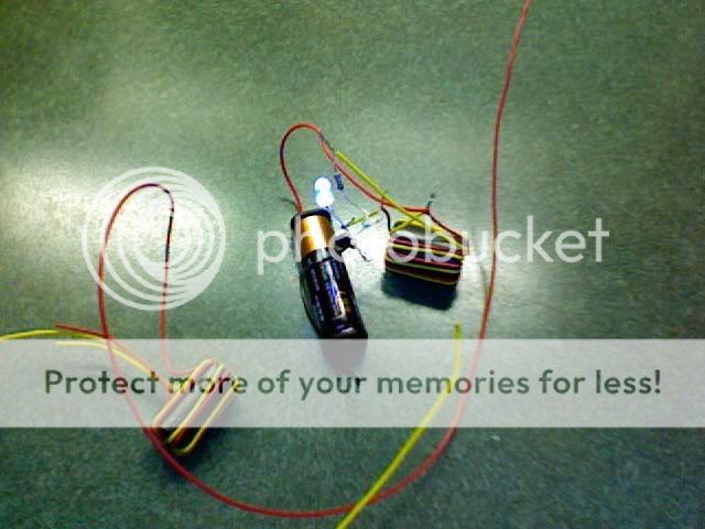
crude but effective . Again this ferrite donut came off a computer monitor cable. Tthe wire is 26 AWG solid , two colors so I could keep them straight.
I was able to get 7 time around without any overlapping . From what I've seen
I don't think it matters if they overlap as long as you don't twist the pair .
This Led has been lit 5 days from a spent AA battery.
Photo33.jpg

Here's the link :http://www.instructables.com/id/SGAUQ04FCEILXWQ/

Does anyone know anything about this homemade driver ??? I have the parts but I need to know what color resistor to use???
I'm a hacker for sure and not very comfortiable with the calulations .I want to know which resistor to use for a 1 watt ,3 watt & 5 watt LED.
thanks
 
Griff,
Here's the resistor color code:
http://www.elexp.com/tips/clr_code.gif
Not being sarcastic or anything but you'll have to get a pack of resistors from Radio Shack and play around with them to see what lights up the best. RS sells about a hundred standard R values in a bag for a few $$.
Holding the resistor with the 3 color bands toward the left, they're read left to right: 1st#, 2nd#, # of zeros.
So your 1000 ohm resistor is 1, 0, 00 ( 2 zeros), so the colors are brown (1), black(0), red(2)...

I've never seen an analysis of this circuit nor any kind of chart to predict output power ( or even LED current) vs resistor value.

To try to optimize output, play with # of coil turns, and value of the resistor, that is, adjust everything...but not too radically in a single step. :)
Using one 1.5V battery,try a larger R value, say 1200 ohms ( brown, red, red), and then a smaller value say 820 ohms ( gray, red, brown) to see which way to go for the output you want.

However, you may find that you can't get there without going to 2 batteries (3V).
In that case start back with the 1000 ohm resistor and do the "higher, lower" experiment again.
 
Griff,
Here's the resistor color code:
http://www.elexp.com/tips/clr_code.gif
Not being sarcastic or anything but you'll have to get a pack of resistors from Radio Shack and play around with them to see what lights up the best. RS sells about a hundred standard R values in a bag for a few $$.
Holding the resistor with the 3 color bands toward the left, they're read left to right: 1st#, 2nd#, # of zeros.
So your 1000 ohm resistor is 1, 0, 00 ( 2 zeros), so the colors are brown (1), black(0), red(2)...

I've never seen an analysis of this circuit nor any kind of chart to predict output power ( or even LED current) vs resistor value.

To try to optimize output, play with # of coil turns, and value of the resistor, that is, adjust everything...but not too radically in a single step. :)
Using one 1.5V battery,try a larger R value, say 1200 ohms ( brown, red, red), and then a smaller value say 820 ohms ( gray, red, brown) to see which way to go for the output you want.

However, you may find that you can't get there without going to 2 batteries (3V).
In that case start back with the 1000 ohm resistor and do the "higher, lower" experiment again.[/QUOTE


Thanks for that!!
 
Guys,
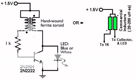
If you don't want to wind the coils, here's a way around it...just a variation of the standard circuit, but using commercial inductors (chokes) like Illum used. Just make sure that the inductors are close together, so their magnetic fields overlap. Note also the winding orientation dots...so if it doesn't work initially, reverse one of the inductors.
JOULEX.jpg

hi flashlife,
When you mentioned "using commercial inductors (chokes)" are you refering to picture 1 or picture 2 below:
Picture 1
100uH.jpg
[/url][/IMG]


Picture 2
220uH.jpg
[/url][/IMG]

I had success using inductor in picture 2. However, they are slightly bigger in size.

Is it possible to use the flat inductor in picture 1 for Joule Thief ? If I place them parallel & close to each other but not touching.

Looking forward to your advice. Thank you
 
Last edited:
Top