Kaidomain "Highly Efficient" Driver Query

bogster

Newly Enlightened
Joined
Sep 16, 2009
Messages
20
I have used one of these drivers:

http://www.kaidomain.com/ProductDetails.aspx?ProductId=1640

(also referred to as kennan) successfully in a 4 XP-G 2S2P setup to give me 500 mA to each LED. I have read several threads here about modifying this board to give different output currents by changing the value of the R2 resistor.

It started me wondering whether or not it might be possible to remove the R2 resistor and replace it with a pair of switched resistors so that you could switch between two different output currents.

From the AX2002 data sheet the value of the R2 controlling resistor should be:

LED output current = 0.25/R

Therefore according to my calculations if I wanted say 1.4A and 700 mA output current I would need resistors of 178 ohms and 356 ohms. My local electronics store lists values of 180 ohms and 360 ohms (0.6W) which should be close enough for my purposes.

Is this a viable option?


Regards,


bogster
 
In that formula you should put current in Amperes and not in milliAmperes, so to give 1.4A of output you should use a 1/2W 0.18 Ohm and for 0.7A 1/4W 0.36Ohm. With the values you listed you would get an output of 1.4 or 0.7 mA, which is way too low to get a useful light and the driver may not even work well due to working at such a low current.
 
Check the diode on your KD1640. The KD web site photos show an SS14 Schottky diode and the corresponding datasheet says it is rated to 1A max average forward rectified current. My modified KD1640 that is set up for 1400mA nominal uses an SS24.
 
Last edited:
Check the diode on your KD1640. The KD web site photos show an SS14 Shottkey diode and the corresponding datasheet says it is rated to 1A max average forward rectified current. My modified KD1640 that is set up for 1400mA nominal uses an SS24.

The Shottkey diode on my board is SS14 but I have no idea what that implies in respect of my initial query.

In that formula you should put current in Amperes and not in milliAmperes, so to give 1.4A of output you should use a 1/2W 0.18 Ohm and for 0.7A 1/4W 0.36Ohm. With the values you listed you would get an output of 1.4 or 0.7 mA, which is way too low to get a useful light and the driver may not even work well due to working at such a low current.

Thanks for the correction italianboy. As you can probably tell I'm quite new to this game and feeling my way.

Therefore if I use the 2 correct values for the resistances that you specify will I be able to connect them in such a way as to be able to switch between the two output currents of 1.4A and 700mA?

Thanks for the replies,

bogster
 
1A < 1.4A.

I'm with you now Justin. Sorry to be so dense but I am a complete newbie with electronics and don't know what a Shottkey diode is or what it does. In potentially boosting the output current to 1.4A I thought it would just be a question of lowering the R2 value as outlined in this thread.:

http://forums.mtbr.com/showthread.php?t=492861

Would you mind taking time out to explain if this is not a good idea?

Regards,

bogster
 
People overdrive components all the time. Your personal comfort level with this and your requirement for product reliability might dictate how you proceed. Seems pretty clear that folks are mod'ing the KD1640 for more current output and the driver is surviving so far. But their usage pattern, how hard they run their gear, etc is unknown to me so I can't comment on how long the driver might survive. Since the driver costs $4, it is probably more trouble than it's worth to find a replacement diode (although sometimes you can scavenge one from another cheap Chinese driver -- for example, the driver in the DX11836 drop-in uses an SK34 diode rated at 3A), remove the SS14, and solder in the replacement. I'd probably just buy 2-3 drivers, mod the sense resistors for 1.4A, and use it as-is. The others can be backups if some overdriven component fries.

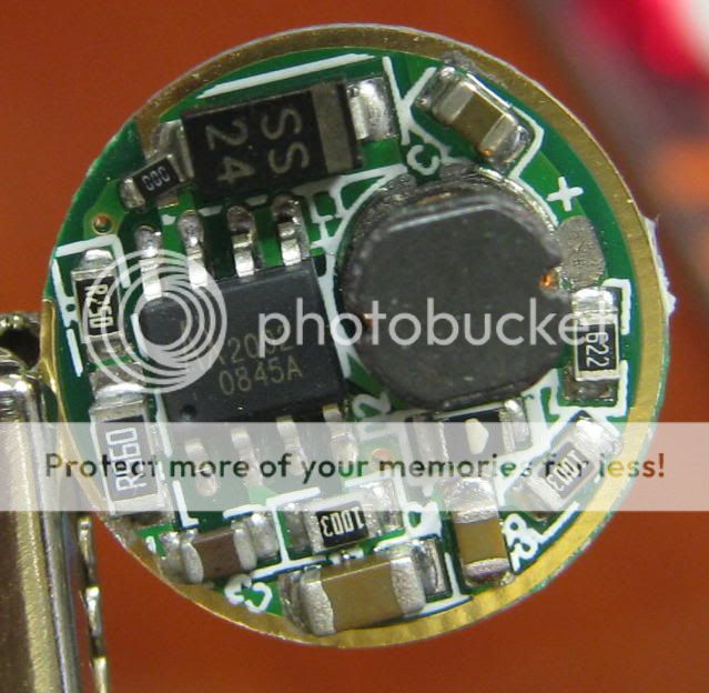
This is one of my 1.4A modified KD1640 drivers. The Schottky diode is an SS24, rated to 2A:
TLST5driver.jpg
 
Last edited:
Justin Case,

Thanks for taking the time to explain that to me it makes more sense now. However I am a bit confused about your later post regarding the current sense resistor. I was under the impression that it was the resistor which is marked on the PCB as R2 and R250 in your picture which would confirm the 1A output current.

Also which is the R220 resistor you refer to because I can't see one marked as such in your picture.

Could you clarify this please?

There seem to be so many versions of this driver around it's all getting a bit confusing.

Regards,

bogster
 
The board in my photo is mod'ed. Rich_SC asked about the drive current for the unmod'ed KD1640. See the photos of an unmod'ed KD1640 in the link that you yourself provided in Post #1. The R220 resistor clearly appears.

Both the R560 and R250 resistors are the sense resistors. They are in parallel (effectively 0.17 ohms), giving a nominal 1.4A out. The stock, unmod'ed KD1640 typically uses just one resistor (as shown on the KD web site), an R220, although apparently some recent versions use two resistors, an R27 and 2R2 (effectively 0.24 ohms).

It's all becoming clear now Justin, thanks for you explanation. I have the newer boards that have the two resistors in parallel giving 0.24 ohms.

Okay, with what I have learnt from this invaluable thread could someone confirm if these are the mods I need to make now to achieve my original aim i.e. dual switching between 1.4A and 0.7A?

1) Replace SS14 Schottky diode with an SS24
2) De-solder R27 and 2R2 resistors
3) Replace 2R2 with R36 resistor
4) Solder another switched R36 off-board in place of R27

This should give me around 0.7A when the switch is open and 1.4A when the switch is closed.

Regards,

bogster
 
I just took delivery of some of these DX "kennan" style drivers:

http://www.dealextreme.com/details.dx/sku.26110

4092960156


The R2 resistor is rated at R20 which would imply an output current of 1.25A if my maths is correct. The Schottky diode is an SS34 which is rated up to 3A (thanks Justin Case!).

If the above is true it would seem to be a better version of the driver than the current KD one. I'm intending to use this driver in my next DIY LED light so will post in future how it turned out.

Regards,

bogster
 
Top