Mattaus
Flashlight Enthusiast
Hi all,
About a year ago whilst in the Jungle of Thailand (seriously - I rode and slept with Elephants man!) I came up with the idea of building a light with multiple emitters of varying capabilities. The ultimate camping light of sorts. Through a combination of "too hard basket" and too many other projects, it got put off constantly. I then stumbled across a light that sort of did what I had in my head but on a smaller scale and I knew it was game on
I purchased some pre-programmed PICs from a developer and went about designing the driver for the light around the firmware and MCU. I chose the SRK as the host because it's cheap, has a relatively compact size (but tonnes of space to add goodies) and massive battery pack. I've also always been a bit of a fan of Lux-RC 3-UP driver-LED combination boards so wanted to design something that reflected that look. In my head it looked really cool!
Took a while to get these finalized because I kept changing my mind and the visual aesthetics probably took far too much of the design up, but once it was done I was pretty happy with my layout.
Blank boards as received from OSHPark:

I actually made a fairly major boo-boo on these boards. I'm not used to working with XQ emitters and the fact they have no neutral thermal pad was forgotten when I performed the layout. As a result I managed to bridge the LED+ pads of the 3 color emitters to the GND pad. I shorted an IMR cell testing the circuit and managed to singe a fairly substantial line into my index finger. This was fixed by cutting around the bridged area. It's all on the backside and covered in a lot of thermal glue so will never be seen and cannot cause me any issues.
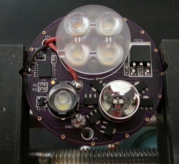
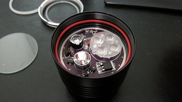
Assembled and tested:
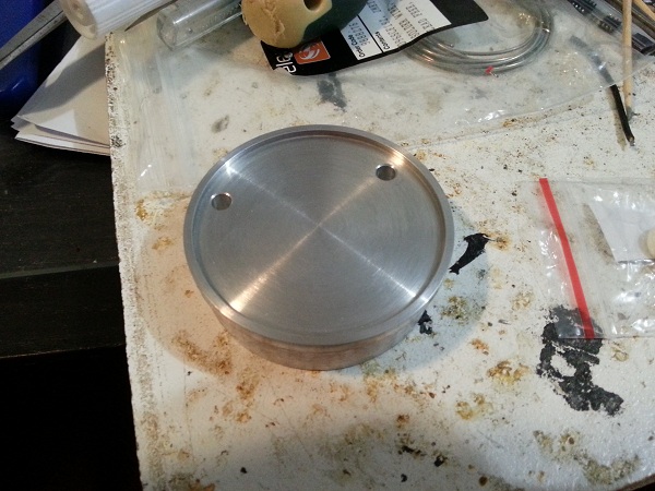
The heat sink was machined by a member here. It's a perfect fit. Fits really well and boy does it suck the heat out. Much more than I expected. If I leave the light on for even a short period of time I can feel the head noticeably warm up which means the heat is being pulled from the main emitters.
I drilled two holes for battery and switch lines myself as they were in really odd places:
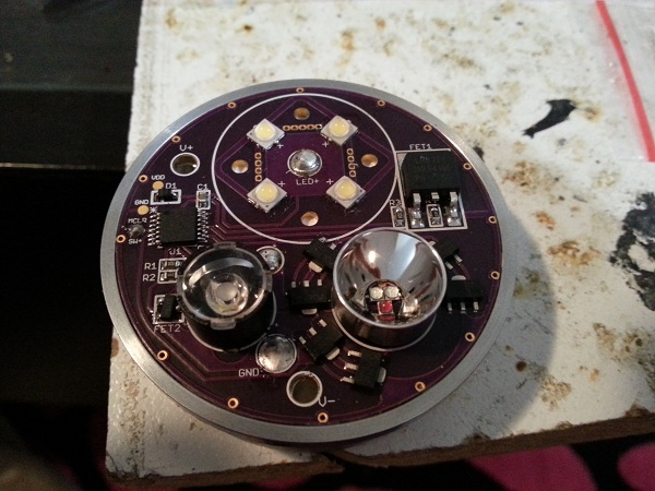
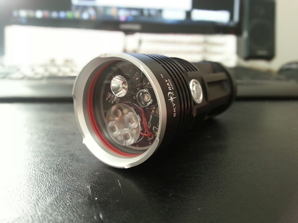
Medusa board test fit. Sexy:
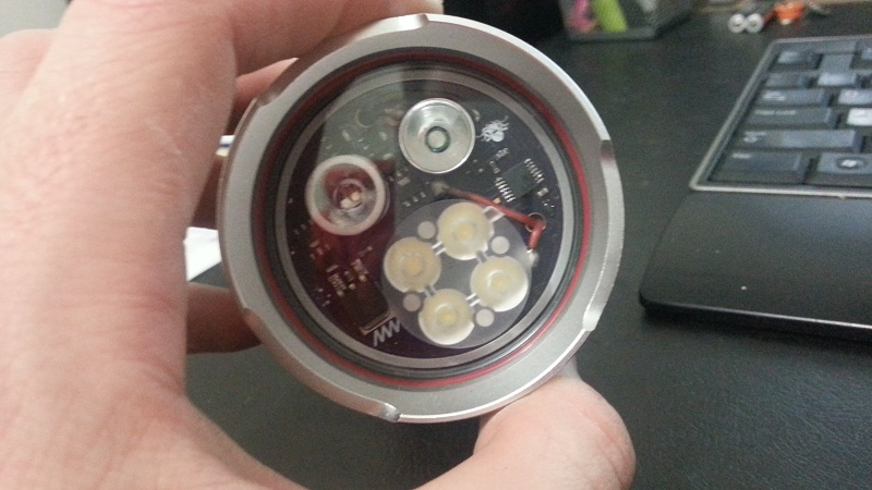
Installed in the SRK head. Like a glove. Unfortunately I glued EVERYTHING with 2 part thermal paste. It's never coming apart:
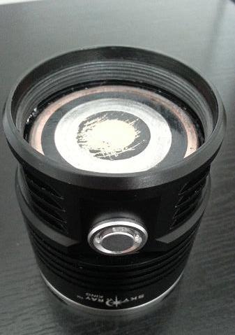
The red orings were created using silicon wire and glue. I needed to sit the lens a tad bit higher than stock so used an oring that sat on the lens shelf to do this. As a result the top oring needed to be thinner so I made another from the same stuff. The double red ring looks cool in my opinion
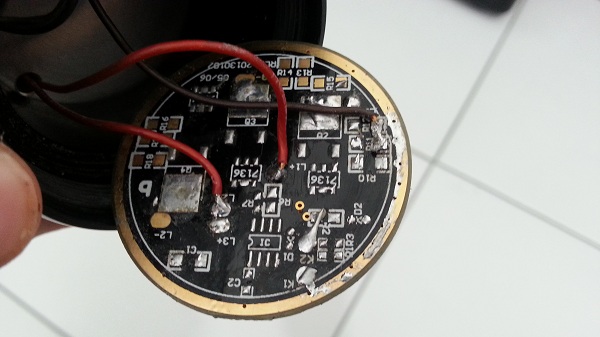
I used the existing SRK driver as the contact plate by stripping it bare, but I plan to design and make a new contact plate that looks a lot nicer:
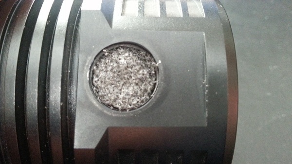
When I first got the SRK I could not recall the switch rattling. But it did after reassembly so I put some soft foam into the cavity on top of the switch before screwing the button and shroud in place. Zero rattle and a nice firm feel to it as well:
Assembled head (with heavily sanded contact plate whilst trying to trouble shoot):
Viola!!!!
...and it didn't work. Well it did, but as soon as I screwed the battery pack in it just started flashing. I tried different batteries and sometimes it worked, whils other times it'd just go back to flashing. It drove me nuts! Spent 2 days trouble shooting:
I eventually figured out that the driver did not like fully charged batteries, but worked fine when the cells were at their nominal voltage (~3.7V). A suggestion was made that the current drain from the white emitters was so high on fully charged cells that it was pulling the voltage too low and resetting the MCU constantly, hence why it worked on more depleted cells and not on fresh cells. The fix was to add a small capacitor between VIN and GND after the reverse polarity diode. In my original circuit I had it placed before the diode. Annoyingly enough this is the first time I've ever done that trick and normally place my caps right on the VIN pin of the MCU!
I happened to have already added a small pad for the GND connection (for programming the PIC) very close the VIN pin of the MCU so I soldered straight to that. Lucky!

Now it functions exactly as described here, just with a MUCH brighter white (I did not write the firmware and the PICs were purchased pre-programmed).
Specs:
I'm going to get rid of the XPE2 and replace it with a UV emitter (still need to find a suitable one at a decent price). This is the because the XPE2 beam is ugly as all hell and doesn't throw nearly as far as I hoped. I'll have to create a board to piggy back a UV emitter and current limiting resistor to the existing XPE pad. No optic will be used for the UV emitter. I'll swap out the Carclo medium quad for a narrow frosted as well.
Beam shots to follow when I can get my hands on a decent camera with manual settings.
Cheers,
- Matt
About a year ago whilst in the Jungle of Thailand (seriously - I rode and slept with Elephants man!) I came up with the idea of building a light with multiple emitters of varying capabilities. The ultimate camping light of sorts. Through a combination of "too hard basket" and too many other projects, it got put off constantly. I then stumbled across a light that sort of did what I had in my head but on a smaller scale and I knew it was game on
I purchased some pre-programmed PICs from a developer and went about designing the driver for the light around the firmware and MCU. I chose the SRK as the host because it's cheap, has a relatively compact size (but tonnes of space to add goodies) and massive battery pack. I've also always been a bit of a fan of Lux-RC 3-UP driver-LED combination boards so wanted to design something that reflected that look. In my head it looked really cool!
Took a while to get these finalized because I kept changing my mind and the visual aesthetics probably took far too much of the design up, but once it was done I was pretty happy with my layout.
Blank boards as received from OSHPark:
I actually made a fairly major boo-boo on these boards. I'm not used to working with XQ emitters and the fact they have no neutral thermal pad was forgotten when I performed the layout. As a result I managed to bridge the LED+ pads of the 3 color emitters to the GND pad. I shorted an IMR cell testing the circuit and managed to singe a fairly substantial line into my index finger. This was fixed by cutting around the bridged area. It's all on the backside and covered in a lot of thermal glue so will never be seen and cannot cause me any issues.
Assembled and tested:
The heat sink was machined by a member here. It's a perfect fit. Fits really well and boy does it suck the heat out. Much more than I expected. If I leave the light on for even a short period of time I can feel the head noticeably warm up which means the heat is being pulled from the main emitters.
I drilled two holes for battery and switch lines myself as they were in really odd places:
Medusa board test fit. Sexy:
Installed in the SRK head. Like a glove. Unfortunately I glued EVERYTHING with 2 part thermal paste. It's never coming apart:
The red orings were created using silicon wire and glue. I needed to sit the lens a tad bit higher than stock so used an oring that sat on the lens shelf to do this. As a result the top oring needed to be thinner so I made another from the same stuff. The double red ring looks cool in my opinion
I used the existing SRK driver as the contact plate by stripping it bare, but I plan to design and make a new contact plate that looks a lot nicer:
When I first got the SRK I could not recall the switch rattling. But it did after reassembly so I put some soft foam into the cavity on top of the switch before screwing the button and shroud in place. Zero rattle and a nice firm feel to it as well:
Assembled head (with heavily sanded contact plate whilst trying to trouble shoot):
Viola!!!!
...and it didn't work. Well it did, but as soon as I screwed the battery pack in it just started flashing. I tried different batteries and sometimes it worked, whils other times it'd just go back to flashing. It drove me nuts! Spent 2 days trouble shooting:
- I swapped out the MCU
- I tried every battery I owned
- I rewired the switch several times
- I removed and re-soldered the contact plate several times
- Sanded the contact plate down just in case it was a contact issue
- I swore. A lot.
I eventually figured out that the driver did not like fully charged batteries, but worked fine when the cells were at their nominal voltage (~3.7V). A suggestion was made that the current drain from the white emitters was so high on fully charged cells that it was pulling the voltage too low and resetting the MCU constantly, hence why it worked on more depleted cells and not on fresh cells. The fix was to add a small capacitor between VIN and GND after the reverse polarity diode. In my original circuit I had it placed before the diode. Annoyingly enough this is the first time I've ever done that trick and normally place my caps right on the VIN pin of the MCU!
I happened to have already added a small pad for the GND connection (for programming the PIC) very close the VIN pin of the MCU so I soldered straight to that. Lucky!
Now it functions exactly as described here, just with a MUCH brighter white (I did not write the firmware and the PICs were purchased pre-programmed).
Specs:
- Quad Nichia 219B direct driven using an IRLR8721 FET (for PWM control) via a Carclo medium frosted optic.
- XPE2 direct driven using an IRLML2502 FET (again for PWM control) via a Ledil Real-Spot optic
- XQE Red, Blue, Green each driven by two 350mA AMC chips, through reflector of unknown origin. I had it floating around.
I'm going to get rid of the XPE2 and replace it with a UV emitter (still need to find a suitable one at a decent price). This is the because the XPE2 beam is ugly as all hell and doesn't throw nearly as far as I hoped. I'll have to create a board to piggy back a UV emitter and current limiting resistor to the existing XPE pad. No optic will be used for the UV emitter. I'll swap out the Carclo medium quad for a narrow frosted as well.
Beam shots to follow when I can get my hands on a decent camera with manual settings.
Cheers,
- Matt