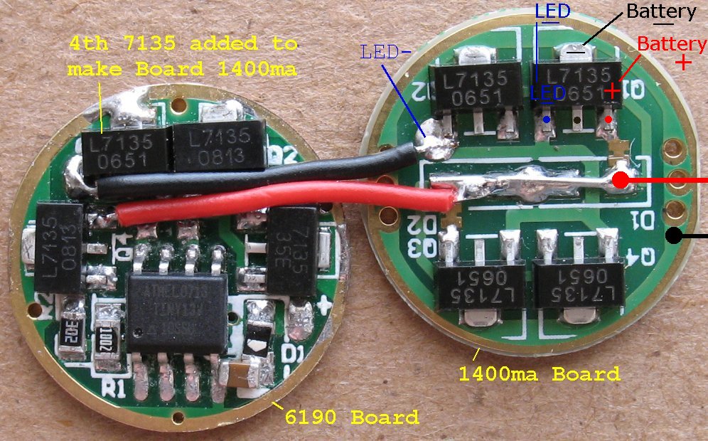
New SKU6190 1050ma board

EL34

Newly Enlightened
Joined
Jan 11, 2009
Messages
65
Just got 3 of the SKU 6190 1050ma boards from DX.
They have changed the design.
It's a much cleaner design, design wise and solder wise than the older boards.

Some of the changes I see so far:

Will only accept/has space for 3 of the 7135 current limiters. The old board had 3, but had a blank space for a fourth one. On the old board, you could add a fourth 7135 to make the board 1400ma.

Has the same ATMEL 0713 - TINY13V - 10SSU IC chip, but the board now has solder traces leading to a few of the legs and there is space for components on the board that lead to those legs. Some sort of future features that can be added????

The rear of the board looks different now. It now says AK-47 and there are 4 new solder points that pass through the board to the ATMEL IC chip legs.

I am curious about these board features and what can be done.

Just thought I'd pin out this board because others will start receiving them soon, if not already.

If anyone spots any mistakes, I'll edit the photo image and correct it.

SKU6190B.jpg
 
Good job on the board layout.:)

I don't think the 5-mode drivers ever had room for a 4th chip because of the presence of the controller. Here's NetKidz's P7 driver post showing an sku.6190 that has no room for a 4th 7135 chip. It's obviously different than yours. This post is over a year old and yet has no vacant spot for a 4th chip. Perhaps you were thinking of the single mode 1050 ma board? This one only has 3 chips with an empty space for a 4th if you happen to have one.

Will only accept/has space for 3 of the 7135 current limiters. The old board had 3, but had a blank space for a fourth one. On the old board, you could add a fourth 7135 to make the board 1400ma.
 
Howdy, I have one of the previous 5 mode 6190 boards here.

Here's a shot of it, notice the empty slot in the upper left.
That's a spot for another 7135.
All the pads are present and in parallel with the other 7135's

There's another design older than this one, maybe that's the one that only has room for 3????

AMC7135.gif
 
Last edited:
Sorry, my mistake. That is interesting though. So many versions, it's hard to keep track of them all.
 
So far I have only used single mode drivers...

With these multi mode drivers, do you have to use a momentary switch, and every time you hit the switch, it changes modes?

Thanks,

dj
 
Tell you the truth, I don't know. I picked one of these up a month or so ago and have not been able to test it yet.

I am running SSC P7's at 2.8 amps and I also needed the 1400ma boards in tandem with the 6190.

The plan was to add one more 7135 to the 6190 board, which would make 4 of them and 1400ma. Then piggy back a 1400ma board to the 6190 to make 2800ma.

Of course, DX was completely out of all of the 7135 boards and so I have been waiting for my 1400ma boards to arrive so I can begin testing.

I have one of the older 6190 boards, and 3 of the new ones, so I can add one more 7135 to that older board for my test and I am designing a 7135 board that can accept up to 8 of the 7135's.

Since the 6190's are add on boards for flashlights that have clicky switches, I am assuming you don't need a momentary switch. Each click brings on the next mode?

The clicky switches I am using have 3 positions. Off-on-on and I am not sure how to wire up the current limiting/mode boards using that switch.

Someone may jump in and enlighten us.
 
The clicky switches I am using have 3 positions. Off-on-on and I am not sure how to wire up the current limiting/mode boards using that switch.

Just so I am clear, the switch you have, you push it once, and it connects circuit one, push it again, and it connects circuit two, push it again, and it disconnects all circuits? I need a switch like that... If what I said is right, could you tell me where you got it, and a part number?

dj
 
yes, you are correct.
click once - position one is on
click again - position two is on
click again - the switch is off

Several of the small clicky switches on DX all do the same thing.

here's the one I am using
http://www.dealextreme.com/details.dx/sku.5618

SWEET!!! I have been looking for just that! Any chance you could post some dimensions of it?

dj
 
They are 12mm square and 7mm high.

I'm about ready to test the 6190 board.
just got a shipment of 1400ma current limiter boards in.
I'll be back later with the results.
 
Last edited:
Please excuse my post as I'm a virgin still!!
These boards that you mention, are they the only electronic bit you need to mod a torch/flashlight.
I have a 6V worklight, but the output is laughable, was thinking of one of these SSC P7 things, maybe a few, what would I need to control these, a board like this ?
thanks,
tabetha
 
I don't mess with flashlights, so I don't know.
You can find info on modding flashlights on this forum.

I build scratch built bike lights using the SSC P7 and custome made cases.
 
I don't think AMC7135's would work very well with a 6 volt source. They are linear buck regulators that have to dissipate all the extra power as heat. Plus they require modification to deliver full power to a P7. Here is the Driver Board List over in the Flashlight Electronics - Batteries Included forum. It hasn't been updated in a little while. Since then TaskLED came out with the hipCC and the more complex hipFlex. And the Shoppe came out with the Shark Buck. These 3 are made for the higher power requirements of the P7 and the MC-E.
 
Ok, just finished testing the 6190 with one more 7135 added to make it 1400ma.

Then I piggy backed a 1400ma board to make the whole assembly 2800ma.

I hooked the assembly up to a SSC P7 LED that was drawing over 3 amps when connected directly to a battery pack. Just a quick hookup for reference so that I did not fry the P7.

You can see the results of the 5 functions and current draws of each function on this page I set up.
http://www.el34world.com/Misc/bike/BikesLights20.htm

6190_2800maA.jpg
 
Forgot to mention that you do not have to click the switch 3 times to get the next mode to happen.

Once you are in a mode, you can just press the clicky switch lightly until it disengages, wait maybe a second or two and then release it.

This acts just like a momentary switch and brings on the next mode without cycling through the switch 3 times.
 
Buried on page 115 (!) of the extended ATtiny13V datasheet is/are the Electrical Characteristics. Each I/O pin can handle 40 mA maximum. Each AMC7135 needs 200 µA.
 
Looking at Re 17

Just an idea:
I think it would be possible to sandwich/backpack on each AMC7135 on the 6190 board a second AMC7135.
So you can save space and get rid of the board holding the 4 AMC7135.
 
Top