
archer6817j
Enlightened
Hi all, I've been playing around with reed activated MOSFET switches. It took a long time to learn and understand the information I needed since I'm not an electronics person.
I thought I'd post this diagram to help others that want to make this type of switch but don't necessarily have the know how. I also wanted to go with a "non technical" diagram so it can be more easily understood for those of us who aren't electrical engineer types.
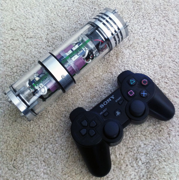
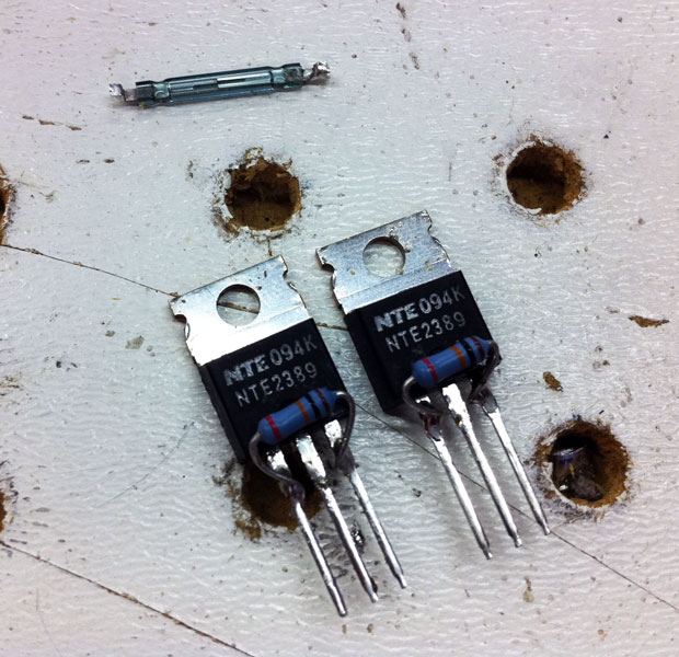
Other types of MOSFET will work but I picked this one up at Fry's without having to mail order anything. Same with the resistor. This particular MOSFET package is fairly small (good for installing in a light) but I'm not sure what the technical "package size" is. The drawing is not to scale of course.
I have this circuit "working" in a light but I wanted to check with the experts here with respect to the location of the resistor. Do I have it right? Are there any other errors on the diagram? The MOSFET is intended to work with an 18650 battery (or similar) because the gate threshold is 3.0V If you wanted to use lower voltage batteries you might need a MOSFET with a lower threshold voltage. The threshold should be less than the lowest charge state of your desired battery configuration. Then all you need to know is the current capacity of the MOSFET. In this case 35A is more than enough")
Thanks in advance and I hope someone finds this useful!
NOTE: the colors on the resistor are not accurate, I just made them up to illustrate the fact that it's a resistor.
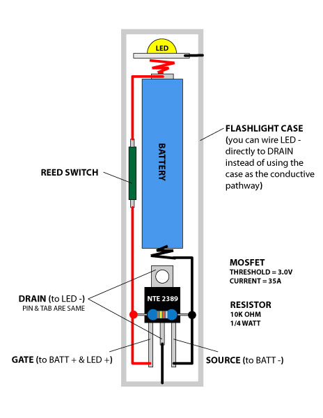
EDIT: DO NOT USE THE NTE2389, IT WILL OVERHEAT
I pulled this link from a recommendation below for a "better" MOSFET for applications under 6 amps: http://search.digikey.com/scripts/DkSearch/dksus.dll?Detail&name=497-9093-5-ND
I thought I'd post this diagram to help others that want to make this type of switch but don't necessarily have the know how. I also wanted to go with a "non technical" diagram so it can be more easily understood for those of us who aren't electrical engineer types.
Other types of MOSFET will work but I picked this one up at Fry's without having to mail order anything. Same with the resistor. This particular MOSFET package is fairly small (good for installing in a light) but I'm not sure what the technical "package size" is. The drawing is not to scale of course.
I have this circuit "working" in a light but I wanted to check with the experts here with respect to the location of the resistor. Do I have it right? Are there any other errors on the diagram? The MOSFET is intended to work with an 18650 battery (or similar) because the gate threshold is 3.0V If you wanted to use lower voltage batteries you might need a MOSFET with a lower threshold voltage. The threshold should be less than the lowest charge state of your desired battery configuration. Then all you need to know is the current capacity of the MOSFET. In this case 35A is more than enough
Thanks in advance and I hope someone finds this useful!
NOTE: the colors on the resistor are not accurate, I just made them up to illustrate the fact that it's a resistor.
EDIT: DO NOT USE THE NTE2389, IT WILL OVERHEAT
I pulled this link from a recommendation below for a "better" MOSFET for applications under 6 amps: http://search.digikey.com/scripts/DkSearch/dksus.dll?Detail&name=497-9093-5-ND
Last edited:
 either. :thumbsup: