Series/parallel switching dynamo powered lights

kananga

Newly Enlightened
Joined
Nov 1, 2008
Messages
27
I had a random thought the other day:
My pair of series Q2's don't really light up on the 10% grade between me and work. I was looking at Martin's voltage doubler circuit for a solution, when I overheard a coworker saying something about rewiring his guitar pickups to switch between series and parallel.
:ohgeez:
Wait a minute...
:rock:
In parallel, my led's would need half the voltage to light. A dpdt switch could click them over to series for full brightness at speed. That's all well and good, so I figured I'd just do that until I get my hands on an R5 xp-g triple then figure out the voltage doubler.

Except...

Why not do the same thing with 3 led's? #1 and #2 could be switched between series and parallel. #2 and #3 could also be switched the same way. Options would be:

All in series, 500ma to all.
Two in parallel, in series to one more, 250ma to two and 500ma to one.
All in parallel, 166ma each.

One dynamo hub, 3 led's, and two dpdt switches. Low, medium, and high beam.
 
You need to design around the smoothing cap capacitor voltage to make sure you're not introducing your LEDs to 9V when going from 3 in series to 3 in parallel. :poof:

When I was running the doubler circuit on a triple I had plenty of light down to walking speeds, a two LED circuit should be brighter.

Another solution might be completely separate circuits. A full wave with a 20mm triple and a doubler with a single LED.
 
I had a random thought the other day:
....
In parallel, my led's would need half the voltage to light. A dpdt switch could click them over to series for full brightness at speed. That's all well and good, so I figured I'd just do that until I get my hands on an R5 xp-g triple then figure out the voltage doubler.

....

I'm not sure I understand the idea of putting the leds in parallel in order to need half the voltage. The voltage required to get current to flow is the same regardless of whether another led is wired in parallel.

dynamo's produce less voltage at lower speeds, so you need to reduce the forward voltage required by the series string of leds. I've done this by shorting out leds at low speeds, leaving one or two leds still powered. Works well enough, and is simple.

regards,
Steve K.
 
You need to design around the smoothing cap capacitor voltage to make sure you're not introducing your LEDs to 9V when going from 3 in series to 3 in parallel. :poof:

There would definitely be a capacitor or three in there somewhere for surges at switching and flicker reduction. There will be an "off" moment during switching with a potential for higher voltages. Do you know what the lag is like for the hub dynamos? Would you say it's more than reasonable capacitors can be trusted with? Maybe there should be a clamp across each led just for good measure...
 
I'm not sure I understand the idea of putting the leds in parallel in order to need half the voltage. The voltage required to get current to flow is the same regardless of whether another led is wired in parallel.
In series, the voltage required to drive them adds up; two series wired Q2's at 500ma would need 3.3 + 3.3 volts, or 6.6 volts.
In parallel, the current (from a current-limited source) is divided between the loads instead. Each led would see 250ma, 500ma total for the pair, but at the voltage necessary to drive each individually; half the power.
I dynamo's produce less voltage at lower speeds, so you need to reduce the forward voltage required by the series string of leds. I've done this by shorting out leds at low speeds, leaving one or two leds still powered. Works well enough, and is simple.

regards,
Steve K.
:ohgeez:
That's brilliant! Simple and does the same thing I was thinking with less switching. Still has the same potential issues with surge, but I like it! Thanks for the idea!
 
I'm not sure I understand the idea of putting the leds in parallel in order to need half the voltage. The voltage required to get current to flow is the same regardless of whether another led is wired in parallel.

dynamo's produce less voltage at lower speeds, so you need to reduce the forward voltage required by the series string of leds. I've done this by shorting out leds at low speeds, leaving one or two leds still powered. Works well enough, and is simple.

regards,
Steve K.

Hi Steve,

Would it be possible to open and close the switch automatically? Couldn't a couple of transistors do the job (bBut hey, what do I know)? Is there a simple way to monitor the voltage for the switch to come into action?
 
Hi Steve,

Would it be possible to open and close the switch automatically? Couldn't a couple of transistors do the job (bBut hey, what do I know)? Is there a simple way to monitor the voltage for the switch to come into action?

This has been done before, by CPF member Bandgap, and I have a circuit drawn up to do the job (just waiting for enough time to work on it). I don't think that voltage monitoring is the best way to do it, though. My preference is to monitor the frequency of the dynamo's output voltage. At speeds above xx mph, all of the leds are wired in series. At speeds below xx mph, one or two leds are shorted out.

A microcontroller is probably the best way to implement this sort of function, but Mr. Bandgap and I are both using one-shot circuits as a "missing pulse detector" to determine when the dynamo's AC period is above or below the threshold. A second one-shot is usually needed at the output of the first to generate a long pulse that will drive the transistor that shorts out the extra led(s).

that's the quick description. Maybe I can find my schematic and post it.

regards,
Steve K.

Thank you Steve,

I tried to find a circuit in the old threads to no avail although when you start talking about I.C. it is probably well over my head. I'm curious though and others might be interested in the circuit, so if it is not to much trouble maybe you could still post it here.

It is always a pleasure to read your helpful posts,
all the best to you.
 
definitly interested in that circuit!!!!!

okay... the schematic is here:

http://farm4.static.flickr.com/3267/3984952705_6a7ee98d6f_b.jpg

The schematic also includes a standlight design that uses a AA nicad or nimh cell for energy storage, and a little Zetex boost converter to run one of the leds. Of course, I haven't built this stuff yet, so there could still be some tweaking of the design required.

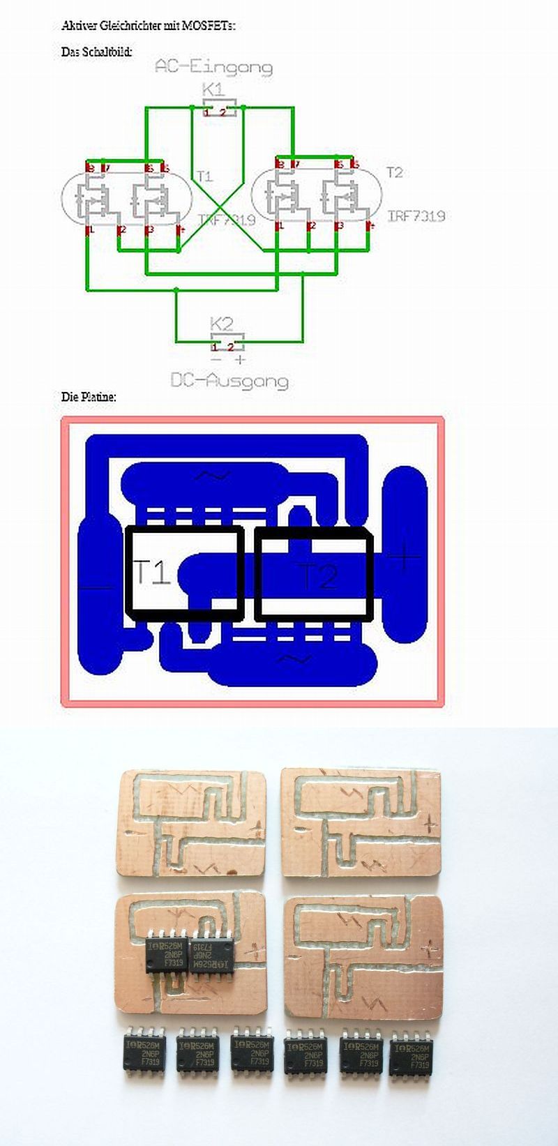
there's also a schematic for a mosfet based bridge rectifier, as an alternate to the standard diode bridge. I need it because I've got a very steep hill on my commute, and I need light at painfully low speeds.

regards,
Steve K.
 
:awman: I knew it :hairpull::hairpull: :eek::eek: ! ;):devil:

what, too complicated?

The circuit isn't that complicated, as long as you break it down into chunks. There's a rectifier stage, a zener clamp, a bit of rectified & filtered power for Vdd, the actual "missing pulse detector" made from the two one-shots, and the somewhat messy drive transistor stage for the mosfet that actually shorts out the leds. It may be possible to simplify the mosfet drive circuit, but the rest is pretty basic (and ancient).

The only real issue, for me, at least, is the size. Well, there's also the issue of trying to hack up a circuit board to create pads for the 0.05" lead spacing on the one-shots. Might try to etch a board, or might just use a "surf board", which is a small circuit board with pads for this size IC. Kinda pricey for what it is.

Steve K.
 
there's also a schematic for a mosfet based bridge rectifier, as an alternate to the standard diode bridge.
known already ;)

b3zyv0pw5wqse5eoa.jpg
 
How's lm3914 (bar graph driver) driven by lm2907 (frequency-to-voltage convertor, sampling dynamo frequency) sound? Plug a few 3914 outputs into p-channel mosfet's, and.....? Just a slightly rewired led bar-graph tachometer.

Shouldn't be too much more intimidating than the auto-switching voltage doubler, but it'll have more operational range!

In principle, that sounds like it could work. It would be a matter of personal taste as to whether the benefits justified the complexity.

I've been distracted and haven't wired up my auto-switching circuit yet. However, in on the road tests, I've used a switch to go from two leds to 4 leds, and the difference is not that significant. If you do have multiple switch points, make sure that the change in light is a factor of 2 or larger.

If you do enjoy complexity for its own sake, it might be interesting to switch between leds with different beam patterns too. At low speeds, a wide beam might be best., especially to allow visibility into a sharp turn. At high speeds, a tight beam may be best to see far down the road.

I sort of split the difference, using different optics on my leds, but going for semi-simple electronics. The biggest factor for me was the realization of how much board space would be needed to implement a more complex circuit, and how limited the available space was.

regards,
Steve K.
 
Top