starting a new project, bezels and tails

DrafterDan

Flashlight Enthusiast
Joined
Jul 28, 2013
Messages
1,317
Location
Phoenix, AZ
Ah yes, tomorrow. That day that never comes. Or at least not as you'd planned it would. I did finish up the tailcap on Saturday. Have to build the light engine for it this week. Here's the one shot I took. Funny that I usually get too involved in the process to remember to take photos...

20160213_131027_1.jpg


While it worked, it didn't turn out as clean as I would have hoped. Need to remake this in steel so I can tighten the bolt holding the tailcap more. Otherwise it slips, and causes far more headaches and design recalculations.
 

Modder

Newly Enlightened
Joined
Aug 25, 2013
Messages
74
Location
Miami
looks nice ! did you have a chance to make some vids also ? would be nice to see that all in motion (or slo-motion, if you have an iPhone :p )
 

DrafterDan

Flashlight Enthusiast
Joined
Jul 28, 2013
Messages
1,317
Location
Phoenix, AZ
Android to the bone here. I believe they do have an app for slow-mo videos, but I've not looked into it. My wife did buy me one of those small action cams, so maybe I can rig up a gooseneck mount for the lathe!

I was waiting to post anything more until I finished with the light engine. My first ever reflow of LEDs onto a MPCB. As this quad is a pretty custom board, I had little choice but to attempt it. I will just say that I'm glad I purchased an extra XPL-Hi.

On with the show!

20160221_221329.jpg


I put one of DellSuperman's 10a Judco switches in this, such a nice firm click sound!

20160221_221340.jpg


The business end.

20160221_221414.jpg


One of Silva's excellent brass mule bodies. DSCHE made the mpcb, and XPL-Hi emitters from Mountain Electronics. I took the easy way out and did a jumper thing between the two sides of the board on the +

20160221_221619.jpg


Running Mountain Elec's FET driver, which has a really fun moonlight mode. Just a four speed, which is great for me, including a 30-second turbo. The high is almost stupid-level bright :) It's definitely taxing my IMR 18650.
Of course, with such a low low mode, I can see the scratch I somehow got on the inside of the lens...

20160221_221811.jpg


It does make a nice overlapping rings kind of design at the edge of the beam. I'll try to do a beam shot at some point.

My first complete body. I can readily say that I learned quite a bit of what not to do for the next project!
 

bartko09

Enlightened
Joined
Apr 11, 2015
Messages
535
Running Mountain Elec's FET driver, which has a really fun moonlight mode. Just a four speed, which is great for me, including a 30-second turbo. The high is almost stupid-level bright :) It's definitely taxing my IMR 18650.
Of course, with such a low low mode, I can see the scratch I somehow got on the inside of the lens...

Great work dan! I just flowed some XPE2's myself.


Did you somehow regulate the FETs output? I was using one of Richards 17DDm's. On high I was pulling 18.5A at the tail cap and it was physically de soldering the leads in under 10 seconds using an AW IMR 18650 [emoji33]
 

DrafterDan

Flashlight Enthusiast
Joined
Jul 28, 2013
Messages
1,317
Location
Phoenix, AZ
I'd love to take your money, but then You'd expect me to do something in exchange :)

As for reflowing, I can relay the method I used. I put the MPCB in a clamp holder and used my iron on the underside of the board.

20160221_202608-1.jpg


I used silver-based solder paste for the LEDs themselves, and regular solder for the wire contact points. The amount to use of the paste is less than a grain of rice. Too much and it will clump on the center thermal contact spot and keep the edges of the LED from touching the anode/ cathode sides. Ask me how I know this...

Use as little heat as possible, otherwise it will discolor the mpcb. Just set the LED onto the solder-pasted contact point and heat it up. When it reaches the right temperature, it will settle itself without any touching/ aligning from you at all. That's why so little paste is used. In my example, the anode (the positive side) of the LEDs were facing away from center. The anode side has the little wires at the edges you can just see on the photo above.

I did one at a time, letting it cool down to be able to touch the board with my bare fingers between. This keeps the overall heat down, reducing damage/ discoloration. I found it helpful (per the video that Old Lumens made) to apply a bit of solder to the tip of the iron before applying to the underside of the mpcb. This helps transfer heat from the tool to the piece.

I then used a CR123 primary to test each side of the quad before I bonded it to the pill. Just a super-quick touch of the leads proved that they were working as desired.
 

MRsDNF

Newly Enlightened
Joined
Jan 9, 2014
Messages
143
Location
In the land of Aus
You have one sweet looking custom built light DrafterDan. Its a good feeling when you hit the switch and theres light.:)
 

bartko09

Enlightened
Joined
Apr 11, 2015
Messages
535
I then used a CR123 primary to test each side of the quad before I bonded it to the pill. Just a super-quick touch of the leads proved that they were working as desired.

Much easier way is to set your multimeter to 200 Ohms and connect it to the positive and negative pads. The small amount of volts used in this test is enough to power the LEDs assuming that they're flowed properly.

Another way to tell if they're flowed properly is to place the leads in the same position and run a continuity test. That will also light the LEDs but much dimmer. If you get a positive continuity audible indicator than somethings wrong [emoji6]
 

DrafterDan

Flashlight Enthusiast
Joined
Jul 28, 2013
Messages
1,317
Location
Phoenix, AZ
That's a great idea B9, I will try that (hopefully) tonight.
It does look like I reset the modes to default when I was messing with the leads. I now have default 4-speed. Not a big deal, but I did lose that moonlight mode, which was fun to play with.

~D
 

precisionworks

Flashaholic
Joined
Apr 19, 2007
Messages
6,623
Location
Benton Illinois
Very nice machine work. You've come a long way in a relatively short time.

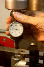
Using a dial gauge worked much better than using the screw table to zero out the threading.
Sometimes called the poor mans DRO. Just as accurate as a DRO, takes a bit more time to set it up. Machinists have used the dial indicator for this function for decades.

Using that half-speed spindle trick worked great, best threading I've produced so far. The power was also cut in half, so I had to manually spin the head in a few places. I'm sure I'm missing something.
When speed is reduced torque is increased. The chuck should be unstoppable at slower speeds.

Turned down a bit of Delrin to contact the tailcap, and it's all held down by a 1/4-20. Now that it's done, it will probably take me a half hour to exactly center it on the table.
IMHO the fastest & easiest way to center on the mill is using a Blake Co Ax indicator. Total time to center is well under a minute using the Blake. Avoid the knock offs as they tend to have a short life, Blakes keep going like the EverReady bunny. They can be used like I did in the image below or you may want to use the included rotation stop rod.

Quite a few listings on eBay right now: http://www.ebay.com/sch/i.html?_from=R40&_trksid=p2050601.m570.l2632.R2.TR4.TRC1.A0.H0.Xblake+co+a.TRS0&_nkw=blake+co-ax+indicator&_sacat=11804

blakeindicator.jpg


Last edited:

DrafterDan

Flashlight Enthusiast
Joined
Jul 28, 2013
Messages
1,317
Location
Phoenix, AZ
Very nice of you to say PW, thank you.

I like that Blake indicator, will keep my eye out for one.

It is strange about the reduced torque when halving the spindle speed. What you say makes sense, but it didn't turn out that way in practice. I may have to do some digging to find the op manual for this beast.

~D
 

precisionworks

Flashaholic
Joined
Apr 19, 2007
Messages
6,623
Location
Benton Illinois
It is strange about the reduced torque when halving the spindle speed. What you say makes sense, but it didn't turn out that way in practice.

Most machines use a combination of belts & sheaves or gears to reduce or increase speed - these behave as expected i.e. the slower the spindle speed the higher the torque. For example, my lathe runs a 3 hp motor & makes about 15 lb/ft at 1750 rpm. That translates to 150 lb/ft at 175 rpm, etc. At 40 rpm, the speed I use for power tapping, the torque is roughly 600 lb/ft. More than most automobiles & even more than many heavy duty trucks.

Some machines use older electronic speed control referred to as V/HZ (volts/frequency). As frequency is reduced voltage is reduced in the same proportion. One half speed means one half torque, one tenth speed means one tenth torque.
 
Top