
Vegeta
Newly Enlightened
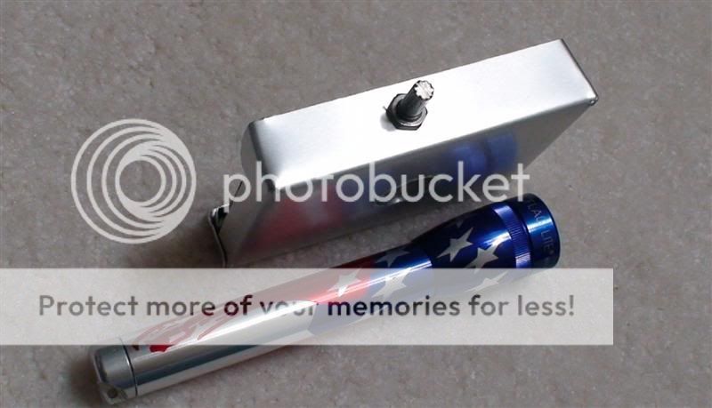
The title is no joke. A vendor at work tried to bribe me into buying some equipment by giving me some a free notebook with a beefy aluminum cover. When I saw that metal plate, I forgot what he was trying to sell and thought to myself, "that notebook is just begging to be modded" and this is the result 

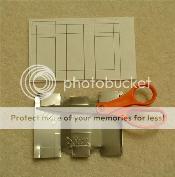
I drew a template on paper and proceeded to cut the sheet with my limited set of tools.
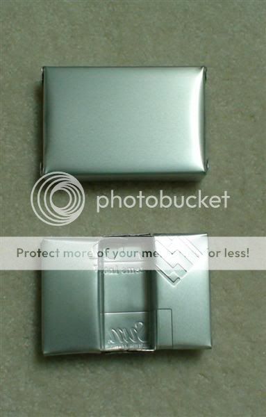
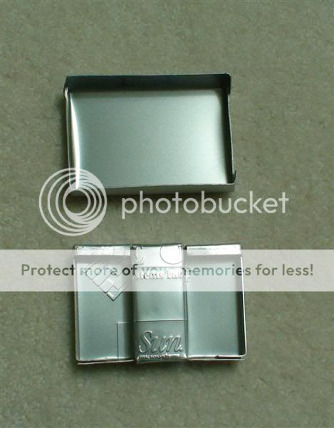
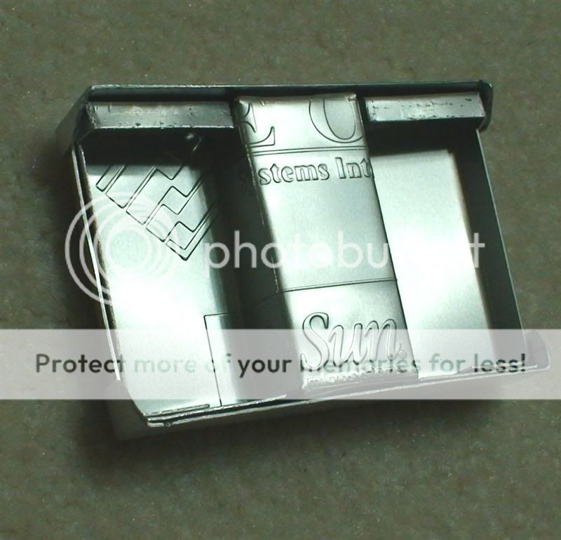
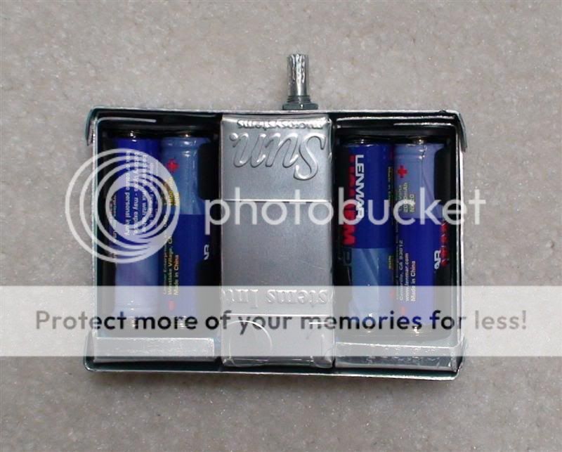
After a few hours of pain and sore fingers, things are finally taking shape. Based on the inscribed text I guess this box will have a little "Sun" inside .
The circuit utilizes the LTC3490 driver but I modified it to go above beyond 350mA while using two cells for the input.
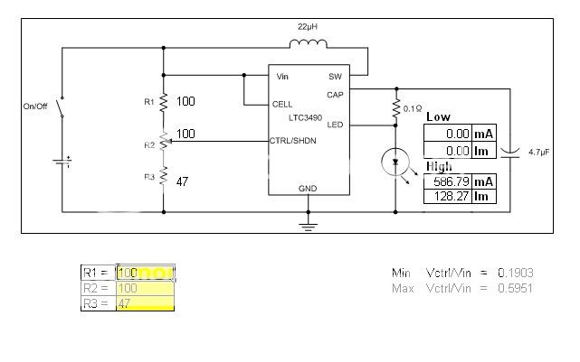
I found that when Vctrl is between 0.2Vin and 0.9Vin, the current output for my particular circuit varied linearly and could be calculated by Iout = 1485(Vctrl/Vin - 0.2)
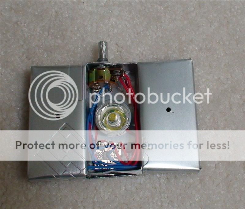
I used a 100K audio potentiometer with a SPST switch to control the output. I added two resistors so that the full rotation of the potentiometer could be utilized for brightness control.

On the low setting, Vctrl is just under 0.2Vin so the light stays off. On the highest setting, I capped it at just under 0.6Vin so my current is limited to 587mA. If I don't set an upper limit, the circuit can actually put out around 1A but efficiency will drop considerably at higher currents. At 587mA output, I am measuring about 90% efficiency and everything runs nice and cool.
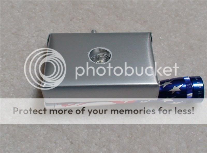
I used a dremel tool to cut the potentiometer shorter and carved some grooves to give it a little more grip. A P4 Cree XR-E was used with an NX05 optic. The optics was a PITA to center but it was all I had. It only takes a few minutes to swap out the optics in the future anyway if I get a hold of something better.
It only needs two cells to run but I put two pairs of cells in parallel to double the capacity. This should more than double the runtime since the circuit gets more efficient when the voltage sag less under load. The useable capacity of the cells should also be greater with the lower current draw.
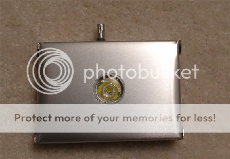
A shot of the LED running at 1mA to show how low it can go. Current draw at the input is about 2mA so you can get some insane runtimes.
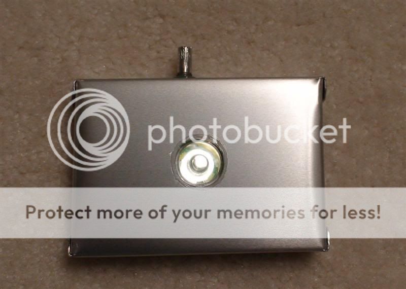
Shot of a wall about 8 feet away with current at 587mA.

A lamp about 8 feet away.

With its super low center of gravity, it becomes the ultimate candle mode light. I built this light as a tent light but I found that it has replaced the lamp on my nightstand .
Unlike some current regulated lights that leave you in the dark minutes after falling out of regulation, this light can be dialed down to give hours if not days of additional low light if you really need it.
I drew a template on paper and proceeded to cut the sheet with my limited set of tools.
After a few hours of pain and sore fingers, things are finally taking shape. Based on the inscribed text I guess this box will have a little "Sun" inside
.
The circuit utilizes the LTC3490 driver but I modified it to go above beyond 350mA while using two cells for the input.
I found that when Vctrl is between 0.2Vin and 0.9Vin, the current output for my particular circuit varied linearly and could be calculated by Iout = 1485(Vctrl/Vin - 0.2)
I used a 100K audio potentiometer with a SPST switch to control the output. I added two resistors so that the full rotation of the potentiometer could be utilized for brightness control.
On the low setting, Vctrl is just under 0.2Vin so the light stays off. On the highest setting, I capped it at just under 0.6Vin so my current is limited to 587mA. If I don't set an upper limit, the circuit can actually put out around 1A but efficiency will drop considerably at higher currents. At 587mA output, I am measuring about 90% efficiency and everything runs nice and cool.
I used a dremel tool to cut the potentiometer shorter and carved some grooves to give it a little more grip. A P4 Cree XR-E was used with an NX05 optic. The optics was a PITA to center but it was all I had. It only takes a few minutes to swap out the optics in the future anyway if I get a hold of something better.
It only needs two cells to run but I put two pairs of cells in parallel to double the capacity. This should more than double the runtime since the circuit gets more efficient when the voltage sag less under load. The useable capacity of the cells should also be greater with the lower current draw.
A shot of the LED running at 1mA to show how low it can go. Current draw at the input is about 2mA so you can get some insane runtimes.
Shot of a wall about 8 feet away with current at 587mA.
A lamp about 8 feet away.
With its super low center of gravity, it becomes the ultimate candle mode light. I built this light as a tent light but I found that it has replaced the lamp on my nightstand
. Unlike some current regulated lights that leave you in the dark minutes after falling out of regulation, this light can be dialed down to give hours if not days of additional low light if you really need it.
