Different Momentary D Mag Switch Mods

Alan B

Flashlight Enthusiast
Joined
Nov 19, 2007
Messages
1,963
Location
San Francisco Bay Area
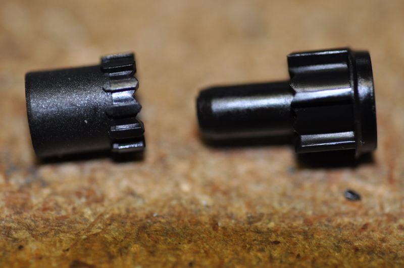
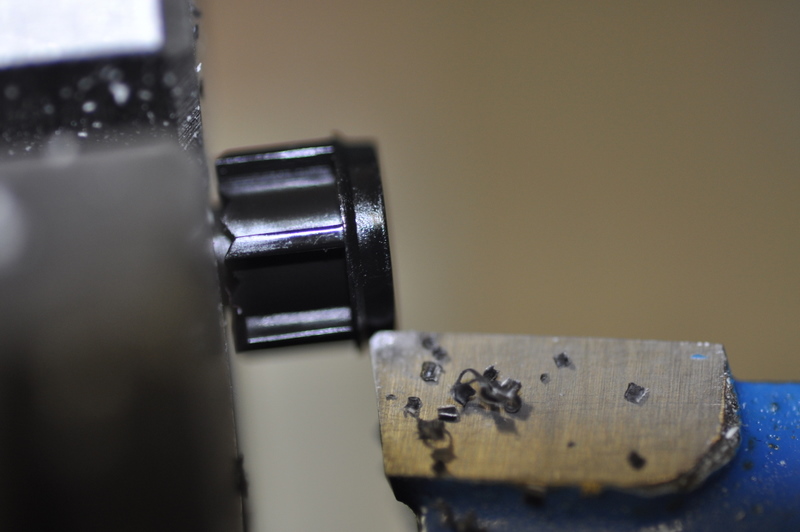
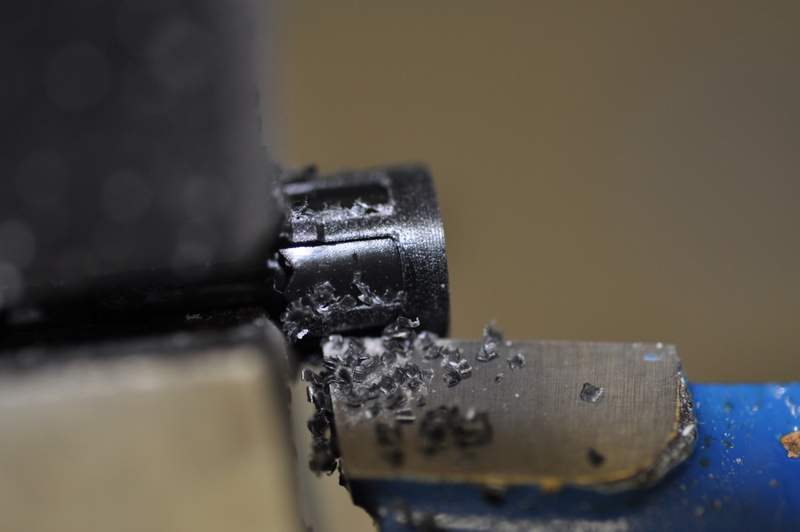
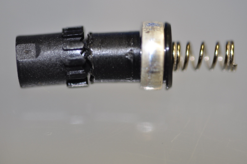
I've been reviewing various D Mag switch mods for momentary use with the d2Flex. Most involve cutting or trimming teeth or ridges. I'm looking at other ways to do this.

Has anyone tried epoxying the two splined parts together, aligned? That would seem to do the same job without all the hacking..??

Here are some convenient links to other threads including D Mag Momentary Switch Mods or other helpful related info:

https://www.candlepowerforums.com/threads/212470
https://www.candlepowerforums.com/threads/90912
https://www.candlepowerforums.com/threads/185436
http://candlepowerforums.com/vb/showthread.php?p=618553
 
Last edited:

Alan B

Flashlight Enthusiast
Joined
Nov 19, 2007
Messages
1,963
Location
San Francisco Bay Area
Re: Momentary D Mag Switch Mod

I made progress today on this, but I decided to try a slightly different approach. I still believe the epoxy approach is a good one, but the problem is how to keep the parts aligned and keep epoxy from getting where it can cause problems.

First a little nomenclature to clarify the discussion. Let's label the switch piston parts starting with the part you push on. Call this part A. The next part is part B. In the following photo part A is on the left, part B on the right:

DSC_0827.JPG


I took a careful look at how the switch locks, which is the function that we are trying to disable. The external ridges on part B do the locking. The part rotates and these ridges slide into slots in the upper switch body. These slots alternate in depth so the switch alternately locks and fully retracts depending on which slots they are aligned with. (Note the ring on the right side of part B. This should be preserved, that was not done the first time around).

So the only ridges that need to be removed are the external ones on part B. Many mods remove the teeth between part A and B, or remove the external ridges on part A. This is not necessary.

So how to remove the ridges from part B.

I decided to try turning part B in the lathe to remove the ridges. Grasping this small part in the 5" lathe chuck on a 10x24 lathe was right at the minimum, but it worked nicely. Part B has a small diameter tube that rides up inside part A, and this was placed in the chuck. The larger diameter portion of part B has the external splines to be removed.. Cutting the splines off required working VERY close to the chuck. Thank goodness for the variable speed mod I did to this lathe.

DSC_0828.JPG


DSC_0829.JPG


I reassembled the switch for testing and it works great mechanically in terms of no longer latching, but the ring that provides the electrical switch action is not correctly retained, so it floats around and does not make reliable momentary switch electrical connectivity.

Shown below is the stack of switch core parts. From the left - A, B, C are the central plastic parts. Around part C is the switch contact ring. To the right is the switch spring.
DSC_0831.JPG
 
Last edited:

Alan B

Flashlight Enthusiast
Joined
Nov 19, 2007
Messages
1,963
Location
San Francisco Bay Area
So there is a small problem with the way I cut the splines off. I also removed the ring on part B that holds the switch ring in place, so it drifts upward.

Next time I will skip over the ring and just cut the spline ridges away. Might have to grind a lathe tool to do that. Actually the tip of the parting off tool blade would do this nicely if I can get it close enough to the chuck. Next time I'll try that. Making a tool is probably the best answer, though.

In the meantime a little epoxy should fix the metal contact ring down where it belongs around part C.
 
Last edited:

Alan B

Flashlight Enthusiast
Joined
Nov 19, 2007
Messages
1,963
Location
San Francisco Bay Area
I fixed the switch ring by epoxying it to part C, and epoxying the part B to that, making sure the central hole is still open for the Allen wrench.
 

Alan B

Flashlight Enthusiast
Joined
Nov 19, 2007
Messages
1,963
Location
San Francisco Bay Area
That was funny. I followed donn's link to where he bought a modded switch, and there was a link there back to this thread. Circular reference! :ohgeez:

I did another one of these mods awhile back and used the cutoff tool on the lathe to slip in there and cut the splines off. But really a little careful work with the xacto knife would be fine. Perhaps drill a hole into a board to stick the part into while working on it and just carve the splines away. Have not tried that but should work fine.

I don't expect this momentary mod to carry much current, it is really just the normal M@g switch with the momentary disabled. But it is fine for those various boards that require momentary.

Have fun!
 

Nanomiser

Enlightened
Joined
Nov 6, 2007
Messages
665
Location
SF Bay Area
I know, I did a little bit of ring around the rosy, but very helpful none the less.

An xacto was exactly what I was thinking. :thumbsup:

The H6Flex will be carrying the real current while the momentary Mag will only see milliamps.

Thanks :)
 

vestureofblood

Flashlight Enthusiast
Joined
Jun 19, 2008
Messages
3,211
Location
Missouri
Could you guys tell me if I understand what is taking place here?

In order to use the D2Flex constant power is supplied to the driver ie a complete circuit even when the light is off. Then when the switch is depressed the current is interrupted and the light comes on/changes modes?
 

Nanomiser

Enlightened
Joined
Nov 6, 2007
Messages
665
Location
SF Bay Area
Basically yes.

As you know the Flex platform offers a number UI options and needs the use of a momentary switch to setup and control these features. So once the Mag switch has been modified and removed from the power circuit it simply acts as a signal generator in order to manipulate the driver. At that point the driver performs the on/off power functions via the switch signal.

I think I explained it correctly; does that make sense? :thinking:


BTW: Great quote from John 1 and God bless. :thumbsup:
 

Alan B

Flashlight Enthusiast
Joined
Nov 19, 2007
Messages
1,963
Location
San Francisco Bay Area
Could you guys tell me if I understand what is taking place here?

In order to use the D2Flex constant power is supplied to the driver ie a complete circuit even when the light is off. Then when the switch is depressed the current is interrupted and the light comes on/changes modes?

Yes, constant power to the D2Flex.

The switch then provides power to the separate control input of the D2Flex when the button is depressed.

It is not interrupting power to the D2Flex, the control input is a separate signal.
 

vestureofblood

Flashlight Enthusiast
Joined
Jun 19, 2008
Messages
3,211
Location
Missouri
Yes, constant power to the D2Flex.

The switch then provides power to the separate control input of the D2Flex when the button is depressed.

It is not interrupting power to the D2Flex, the control input is a separate signal.


Ok so constant power to the driver. Separate wire to the controller that does not have current through it until the switch is depressed?

I have looked over the momentary switch mod links and from what I can tell it appears that there is only one wire going to the controller part. Is this correct? No return wire for a complete circuit?

Like this?
 

vestureofblood

Flashlight Enthusiast
Joined
Jun 19, 2008
Messages
3,211
Location
Missouri
So rather than the second wire I have drawn from the base of the cell I could get my negative power into the switch by connecting to the driver ie SW-?

Otherwise this is correct?
 
Top