Maelstrom X10/S12 direct drive mod that retains low mode!

Colonel Sanders

Flashlight Enthusiast
Joined
Aug 17, 2010
Messages
1,022
Location
ROLL TIDE!
Maelstrom X10/S12 direct drive mod!

I have not tried this on an S12 (my light is an X10) but I'm almost sure that it should work on it as well.

Here is what you will end up with...

Direct drive when on high. Stock is about 3A drive. After this mod you will get whatever your battery will supply. I have seen as much as 5.3A from an IMR26650 charged to 4.25V. I have also seen 3.5A from a partially depleted Redilast 2900mah 18650. It will be noticeably brighter but especially when shining out in the open at long distances. It is very obvious that the throw was increased. I compared it to a couple of my other lights before and after.

More throw! Selfbuilt measured the X10 at 24,000 lux at 1m. Mine measures a solid 31k at 1m and I have measured as high as 34k (short lived).

A nicer beam!
Before, my hotspot was a slightly creamy white with a yellowish corona and a slightly purple tinted spill. There were some artifacts but nothing too bad (mine seems to be better than most of the pics I've seen for some reason.) After this mod everything has been whitened up a bit and the artifacts are a little less noticeable. The hotspot is almost true white now and the corona is a little less yellow. I guess the spill looks about the same.

Low voltage cutoff is retained. I ran the light until it cutoff, immediately pulled the IMR26650, and checked the voltage at 3.09v.

Ok folks, this is VERY simple. I will refer you to some pics in vinhnguyen54's thread (Vinny, didn't think you would mind) for reference. These pics are of an S12 but the layout is the same as the X10.

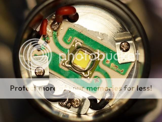
Here is a stock S12...
MaelstromS12LED.jpg


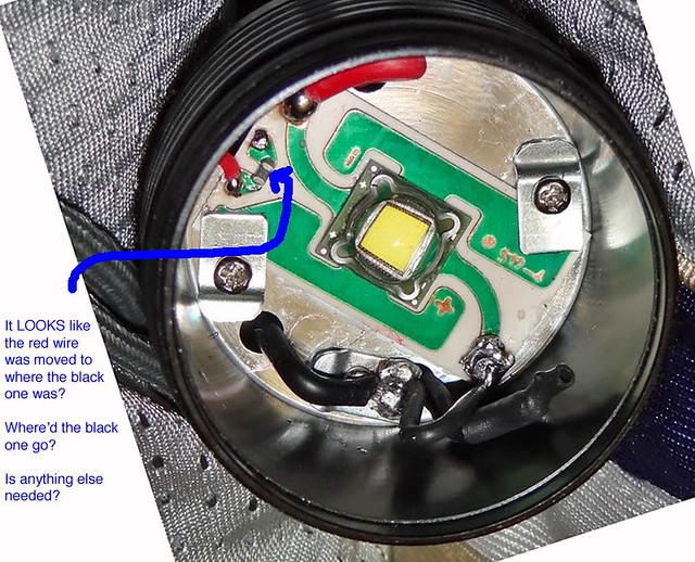
Here is the way Vinny modified it to direct drive...
DSC00071.jpg


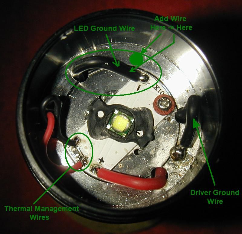
Here's the key...do exactly what Vinny did in this picture but DON'T clip the black wire that connects directly to the negative on the LED as he did. We are simply adding a direct ground path from the LED negative in the same way that Vinny did. The only difference is that we are not going to remove the original ground path from the driver.

So, in a nutshell...Do what Vinny did but don't clip the original ground.

Regarding the thermal management circuit...I don't know if it has to be de-activated in order for this mod to work (mine was already killed before trying this direct drive mod) but I suspect that it probably does. Maybe someone can try it first without disabling the TM and confirm this.

To disable the thermal management, all you have to do is clip either one of the smaller red or black wires located at the 9:30-10:00 position in picture one.

***ONLY DO THIS AT YOUR OWN RISK!!!*** I WOULD EXPECT THE LIFE OF THE LED AND DRIVER TO BE GREATLY SHORTENED BY DOING THIS SO DON'T BLAME ME IF IT GOES :poof: ! There, now you've been warned. :)
 
Last edited:

Colonel Sanders

Flashlight Enthusiast
Joined
Aug 17, 2010
Messages
1,022
Location
ROLL TIDE!
GL, when you get yours opened up, let me know if everything seems clearly explained in this thread. I think it is but I guess I can see where someone might get a little confused as to which is negative (it's the big black wire coming off the LED...5 o'clock position first picture and 11 o'clock position in the second picture) and maybe those pics can be just a tad confusing due to the light being orientated differently from the first pic to the next.
 

Got Lumens?

Flashlight Enthusiast
Joined
Mar 12, 2011
Messages
2,461
Location
Champlain Valley
Hi I just got the X10. I am waiting on the second S12 to get here. That is the one that will get upgraded/downgraded, depending which way you look at it. Also need to get some NiMh's to complete the burn in process like BigC has mentioned previously.
Thanks
GL
 

Colonel Sanders

Flashlight Enthusiast
Joined
Aug 17, 2010
Messages
1,022
Location
ROLL TIDE!
I found out today that the low voltage cutoff is retained with this mod, as I expected, and included the finding in the OP. :thumbsup:

I sure hope some of you try this. So far I have found no downside to this mod other than the expected quicker heat buildup and, of course, shorter battery life. :cool:
 

Got Lumens?

Flashlight Enthusiast
Joined
Mar 12, 2011
Messages
2,461
Location
Champlain Valley
GL, when you get yours opened up, let me know if everything seems clearly explained in this thread. I think it is but I guess I can see where someone might get a little confused as to which is negative (it's the big black wire coming off the LED...5 o'clock position first picture and 11 o'clock position in the second picture) and maybe those pics can be just a tad confusing due to the light being orientated differently from the first pic to the next.

Colonel,
They are not the same. I will post a picture.
Basically the same wires, but alot smaller, probably half the sizes of the S12.
There are no adjustment screws on the X10. I think an easier way would be to strip a little of the black insulation off the Led Ground with an xacto knife, solder a new 16ga wire to it, and solder the new wire to the ~1/4" ring that has the holes for the 2 grounds, positive, and thermal wires.
GL
 

Colonel Sanders

Flashlight Enthusiast
Joined
Aug 17, 2010
Messages
1,022
Location
ROLL TIDE!
Yep, that would work just fine too.

I never meant they were the same, just that the layout was the same. Thanks for the X10 pic. That should make it plain as day for anyone looking to do this. :cool:

So, did you go through with doing this mod? What do you think? And did you leave the thermal management intact or did you clip it?
 

Got Lumens?

Flashlight Enthusiast
Joined
Mar 12, 2011
Messages
2,461
Location
Champlain Valley
So, did you go through with doing this mod? What do you think? And did you leave the thermal management intact or did you clip it?

Colonel,
I am waiting for batteries to do a burn in on my S12. I will be doing the X10 after the S12. I am going to use small automotive connectors to allow me to choose between stock, Thermal disabled, and DD :).
GL
 

Colonel Sanders

Flashlight Enthusiast
Joined
Aug 17, 2010
Messages
1,022
Location
ROLL TIDE!
Sounds interesting. That's gonna have to be some pretty small connectors for the TM on the X10.

I think you're gonna like the X10 set on KILL mode the most. It's my favorite at the moment. :cool:
 

Got Lumens?

Flashlight Enthusiast
Joined
Mar 12, 2011
Messages
2,461
Location
Champlain Valley
Sounds interesting. That's gonna have to be some pretty small connectors for the TM on the X10.

I think you're gonna like the X10 set on KILL mode the most. It's my favorite at the moment. :cool:

I will have to add a little length to the TM wires :) , there is no way I am going to be able to crimp those short leads. Do you have any beam shots of the X10 on kill mode? my recent session with stock was not that earth shattering.
GL
 

Colonel Sanders

Flashlight Enthusiast
Joined
Aug 17, 2010
Messages
1,022
Location
ROLL TIDE!
I guess I need to get off my lazy butt and take some pics (would be my first "beam shots".) I wouldn't call it earth shattering but it surely is my most impressi e light for it's size when direct driven. Most noticably when in the great outdoors looking way out. I live in the country amongst thousands of acres so I really lean towards lights with throw.
 

Jekyll & Hyde

Newly Enlightened
Joined
Oct 1, 2011
Messages
39
I guess I need to get off my lazy butt and take some pics (would be my first "beam shots".) I wouldn't call it earth shattering but it surely is my most impressi e light for it's size when direct driven. Most noticably when in the great outdoors looking way out. I live in the country amongst thousands of acres so I really lean towards lights with throw.

J: Wow. Still trying to digest all of this.

H: What are your thoughts guys after using these modded lights for a couple of months now?

J&H
 

Viper715

Enlightened
Joined
Feb 28, 2009
Messages
691
Location
Missouri
Would like to here long term use thoughts as well. Just got my S12 and want to try this out as long as it is a stable and usable mod in the long run.
 

Patriot

Flashaholic
Joined
Feb 13, 2007
Messages
11,254
Location
Arizona
Colonel,
I think an easier way would be to strip a little of the black insulation off the Led Ground with an xacto knife, solder a new 16ga wire to it, and solder the new wire to the ~1/4" ring that has the holes for the 2 grounds, positive, and thermal wires.
GL

I'm wondering if you would even have to strip the black insulation off the LED ground wire or if you could simply solder the new 16ga wire to the neg solder blob itself. Any thoughts?

I've de-soldered the small negative thermal wire from the thermal regulation circuit. So far all is great and there's no thermal regulation happening. Since I've got the copper version, I'll enjoy taking advantage of its improved thermal properties.
 

TEEJ

Flashaholic
Joined
Jan 12, 2012
Messages
7,490
Location
NJ
MaelstromS12LED.jpg


6775921310_3046d64f5b_z.jpg


OK, I have an S12, but I have no idea what I'm looking at in the pics...I rotated the second one to make it line up with the first one, and I still don't know what part to do/not do...

IE: I understand to "Do what Vinny Did" (Except the ground clipping for the negative)...but I don't know what Vinny DID.

Did something get soldered, or just cut, or what? Which black wire is the ground I'm NOT supposed to cut?


help?

:huh:
 
Last edited:

Patriot

Flashaholic
Joined
Feb 13, 2007
Messages
11,254
Location
Arizona
MaelstromS12LED.jpg


6775921310_3046d64f5b_z.jpg


OK, I have an S12, but I have no idea what I'm looking at in the pics...I rotated the second one to make it line up with the first one, and I still don't know what part to do/not do...

IE: I understand to "Do what Vinny Did" (Except the ground clipping for the negative)...but I don't know what Vinny DID.

Did something get soldered, or just cut, or what? Which black wire is the ground I'm NOT supposed to cut?


help?

:huh:


Clip or de-solder the small black thermal regulation wire at the 10:00 position. Then insulate the loose end. This disables the thermal regulation circuit.

Add (solder in) a by-pass wire (a direct ground path from the LED negative) from the LED negative solder blog at the 5:00 position. Connect the other end of your by-pass wire to the driver terminal (the other solder blob) at the 6:00 position. This disables / bypasses the current regulation.

In Vinny's picture, the large black negative wire to LED has been de-soldered and heat-shrinked, but you don't have to do what he did. Just follow the steps above and leave the aforementioned negative wire to LED alone.
 
Last edited:

Patriot

Flashaholic
Joined
Feb 13, 2007
Messages
11,254
Location
Arizona
Ignore the reversed small black and red wires. I'm not sure why these are two different pictures but they might have been two different lights, one with the black wire removed, another with the red wire removed. If you remove either wire, the thermal circuit will be disabled. Just remember to insulate the exposed end of the loose wire with heat-shrink or something.
 

TEEJ

Flashaholic
Joined
Jan 12, 2012
Messages
7,490
Location
NJ
The red wire at the 10 Oclock position appears to have moved to where the black one used to be, but there's no mention of that red wire being moved...? It would explain the black one being missing...but how is that black one terminated?

Also - I keep looking at the + and - signs on the board, and I'm interpreting the + as being closer to the 5 and 6 Oclock position, that you are calling negative...so, I'm then assuming that the + and - are not really those sweeping green paths from the LED?

(Lots of chemistry and microbiology, no electronics...I see I need to do some reading...)

SO - #1 - Terminate the black wire up by my blue arrow. (10 Oclock)

#2 - Add a jumper between the 5 Oclock and 6 Oclock blobs.


Just missed your follow up - So the red OR black could have been cut/shruck wrapped, etc...didn't matter which at that 10 Oclock location...OK...easier. :D
 
Top