Advice for New project: Home indoor bounce lighting with Cree XP-G LEDs.

samgab

Flashlight Enthusiast
Joined
Aug 23, 2010
Messages
1,259
Location
Auckland, New Zealand
I'm checking for traps and pitfalls with my new project. I have some questions, and appreciate advice.
  • I have some strips of 40mm x 3mm x 1M aluminium bar stock.
  • I've ordered some Cree XP-G LEDs.
  • I have a 13.8 V constant DC voltage power supply, which can supply up to 8A of current, or just over 100W of power.
  • I've ordered some 1Ohm, 2W resistors.
I want to attach arrays of 4 XP-G's to the aluminium rectangular section bar stock and use them for upwards pointing ceiling bounce lighting.
I had a look at http://led.linear1.org/led.wiz and came up with this:
sW25NK

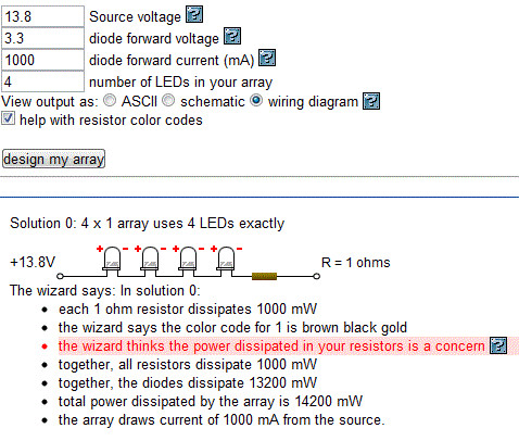
So I've ordered some 2 Watt 1ohm resistors.
I have a few questions and concerns.
  • Will the circuit as described above, connected to a 13.8V constant voltage power supply only draw 1Amp per array?
  • What is the best way to attach the LEDs to the aluminium? I thought of thermal adhesive or thermal tape.
  • I wonder what size power cable is capable of handling 1Amp Current?
  • Is 1Amp a good level to drive the XP-G at?
uXmWp3

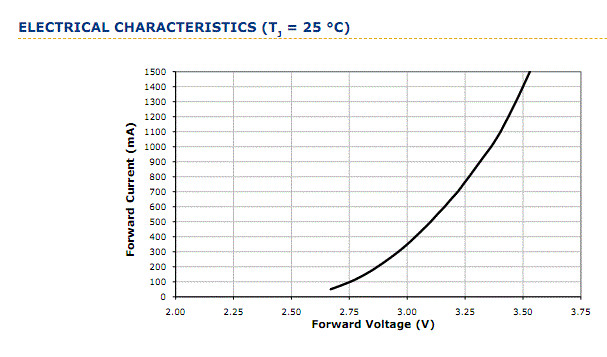
This chart shows that 1Amp current corresponds to 3.3V forward Voltage.
So in a series of 4 that would equate to a 13.2V forward voltage at 1Amp, and I presume that a 1Ohm resistor will equate to a .6V drop?
This circuit will apparently draw 14.2W.
  • Will a 2W power rated resister be sufficient? I think it will, because it will be dissipating 1W, which is only 50% of it's rated capability.
  • Will anything special be required to cool the resister... Maybe if I was to mount it to the aluminium using thermal adhesive also?
  • I'm thinking of also installing a switch in circuit (rather than just turning off the power supply at it's switch) and a 2A (?) fuse.
  • I don't know what kind of switch (prefer illuminated... 12v? 2A? DC?) or what type of fuse... Maybe automotive fuses and switches would be best.
Maybe I could post some pictures when all the parts I require turn up and I assemble it.
If it works well, I might do some more. This is just testing it out really.

With high power LEDs like this, is it okay to use a constant voltage supply and a calculated resistor like this, or must a constant current supply be used?
Are there any websites with tutorials for this type of thing or useful info?

Cheers,
Sam.
 
Last edited:

IMSabbel

Enlightened
Joined
Dec 4, 2004
Messages
921
I would advice against using a constant voltage source, _espcecially_ in case of indoor lighting, which might have long on times.

While a 1m aluminium bar makes for a decent heatsink at 40mm width for the 10W involved, LEDs still have a positive temperature coefficient. And the PSU you are going to use is beefy enough to accomodate any drop in resitance, potentially damaging to the LEDs.

Otherwise, 1A is a perfectly reasonable driving current for XP-Gs.
 

samgab

Flashlight Enthusiast
Joined
Aug 23, 2010
Messages
1,259
Location
Auckland, New Zealand
I wondered as much.
How about this:
http://www.meanwell.com/search/lpc-35/default.htm


I
was thinking the way to go might be to get the 35W, 1050mA version.
This unit is designed to run this sort of high power LEDs like the Cree.
It's nice and simple too.
I can just wire it to a wall plug at one end, and wire it to the LEDs at the other end,
It puts out a constant current of 1050mA (also available in 700mA and 1400mA... Maybe I should get the 1400mA... The XP-G is rated up to 1500mA constant supply...)
and the voltage of the 1050mA one will go up to 30V, and as much as 31.5W.

So I could wire as many as 9 XP-G's up in series, and I won't have to worry about resistors or anything.
Just a simple series. Although to give a safe margin I don't think I'd go higher than 8 in a series.
Although in their rated capacity I'm sure they build the margins in... But nonetheless...
1050mA through an XP-G = 3.3V forward voltage x 8 in series = 26.4V and ~27.7W.

Yes, I think this is a better option.
 
Last edited:

David_Campen

Enlightened
Joined
Jun 29, 2004
Messages
674
Location
California
I have only worked with high power LEDs that are already mounted on star metal clad PCBs so excuse the dumb question but I don't see the CREE XP-Gs being sold on MCPCB so, after you affix the LED to the aluminum barstock using electrically insulating tape or adhesive then, where do you make the electrical connections?
 

samgab

Flashlight Enthusiast
Joined
Aug 23, 2010
Messages
1,259
Location
Auckland, New Zealand
I have only worked with high power LEDs that are already mounted on star metal clad PCBs so excuse the dumb question but I don't see the CREE XP-Gs being sold on MCPCB so, after you affix the LED to the aluminum barstock using electrically insulating tape or adhesive then, where do you make the electrical connections?

Good point. Yeah, I've ordered some XP-Gs with the little aluminium heatsink PCB part already on them. I'll thermal glue the alu heatsink to the alu bar stock... I stuffed up at first... ordered some without the heatsink/PCBs. But I'll also buy some heatsinks for those and use them that way.
See this demo for how that can be done at home:
 
Last edited:

David_Campen

Enlightened
Joined
Jun 29, 2004
Messages
674
Location
California
I would suggest drilling holes into the aluminum barstock and using screws to attach the MCPCB it will be easier to remove or move if you ever want to and you will probably also get better thermal contact. I use Arctic Silver brand thermal transfer compound either the "Arctic Silver 5" or the "Ceramique 2". The Ceramique 2 is almost as effective as the Arctic Silver 5 but is not as messy since it is pure white while the Arctic Silver 5 is gray.

As for wire diameter, I am using 22 gauge wire (stranded, silver plated, teflon insulated) it is good for 1 amp if the length of each lead from driver to LED is less than a couple of meters. I was using 18 gauge but found it to be a bit large compared to the size of the solder pads. Here is a resistance table:
http://www.cirris.com/testing/resistance/wire.html
 

samgab

Flashlight Enthusiast
Joined
Aug 23, 2010
Messages
1,259
Location
Auckland, New Zealand
Excellent info DC, thanks for that. I think you might be right about using thermal paste and screw mounting... I'll look into doing that instead. I want a flat base, so I might countersink some machine screws from the underside, and attach via nuts and washers from the topside. Or maybe get some rubber stick-on feet for the the alu strips which will create clearance underneath for the nuts. I already have a small syringe of arctic silver compound, so I could use that.

I'm still waiting on parts to arrive.

This all began, because I'm using a ceiling bounce light, a powerful halogen type, and I measured it... It runs at 400 Watts at full power.
I think I can get as much brightness from a 30 Watt XP-G setup.

I've decided to use 8 XP-Gs run @ 1050mA each, run in series, spaced over 2 meters of alu strip. No diffusers - they'll just be pointed up at the ceiling for bounce light.
They should run at 8 x ~3.375V = ~27V @ 1050mA
As for lumens, @ 1050mA they should each be ~260% of the rated lumens @350mA, (which is 139 lumens in the R5 type I got (I'll look into warm or high CRI next time round))... Anyway, that works out to about 360 lumens x 8 = somewhere around 2880 lumens at the emitters total output. Less losses due to heat, inefficiency, etc.

I don't know how many lumens the 400W (rated for 500W) tungsten halogen light puts out...
srebEE

Any ideas on that?

(Edit:) Okay, I did some digging and it seems likely that at 400W the tungsten halogen is putting out something like 8000 lumens... But it's far too bright for the purpose anyway, and I can place the LEDs in a better location anyway, so it'll work out alright. Well, I'll see how it goes, and maybe expand the system later...
 
Last edited:

MikeAusC

Enlightened
Joined
Jul 8, 2010
Messages
995
Location
Sydney, Australia
"I use Arctic Silver brand thermal transfer compound either the "Arctic Silver 5" or the "Ceramique 2". The Ceramique 2 is almost as effective as the Arctic Silver 5 but is not as messy since it is pure white while the Arctic Silver 5 is gray."

- whether you use any of these incredibly expensive compounds - or just Lanolin Oil - won't make more than one degree of chip temperature difference - yes, I have tested it.

What will make a big difference is lapping the two surfaces using 800 grit paper, so you get as much METAL-to-METAL contact as possible.

Aluminium has 30 TIMES the thermal conductivity of the best thermal compound.
 

David_Campen

Enlightened
Joined
Jun 29, 2004
Messages
674
Location
California
"I use Arctic Silver brand thermal transfer compound either the "Arctic Silver 5" or the "Ceramique 2". The Ceramique 2 is almost as effective as the Arctic Silver 5 but is not as messy since it is pure white while the Arctic Silver 5 is gray."

- whether you use any of these incredibly expensive compounds - or just Lanolin Oil - won't make more than one degree of chip temperature difference - yes, I have tested it.

Interesting, that contradicts what was reported here:
http://benchmarkreviews.com/index.php?option=com_content&task=view&id=150&Itemid=62

Have you published your test procedure and results here?

What will make a big difference is lapping the two surfaces using 800 grit paper, so you get as much METAL-to-METAL contact as possible.
I polish the mating surface down to at least 1200 grit and then, if I feel enthusiastic, I follow that with polishing compounds to get a mirror finish. The aluminum side of the MCPCB board on the Ledengin 10-watt (LZ4-) LEDs is rough enough that I can feel it with my fingernail so at first I was also polishing this but then I decided that I did not like handling the LED this much and getting aluminum powder and other contaminents on it so now I use it as is without any polishing on my part.

Aluminium has 30 TIMES the thermal conductivity of the best thermal compound.
Only 30 times, I would have thought aluminum would be even better.

So, are you saying you don't using any thermal interface material between your high power solid state devices and the heat sinks? Oh well, to each their own, I will continue to use thermal interface compounds.
 
Last edited:

samgab

Flashlight Enthusiast
Joined
Aug 23, 2010
Messages
1,259
Location
Auckland, New Zealand
All interesting info. I guess I'll take the best of both options; use a cutting compound to lap the Alu to Alu surfaces AND use the Arctic Silver that I already have. Can't hurt, right, even if it's effectiveness is questioned by some. Myself, I figure they must use it on millions of PCs for a reason.
On a microscopic scale, I presume it fills the tiny little gaps caused by microscopic roughness of the two mating surfaces. The smoother both surfaces, presumably the better they will mate together without compound, and the better the heat transfer, so I guess that's why fine sanding helps. Maybe I could solder the Alu heatsink to the Alu strip all the way round... And not use any heat transfer past. The heat dispersion from emitter to heatsink is good because it is soldered down, and the star is a larger mass of Alu. If that in turn is soldered all the way around to a larger again Alu area, it should be fine. Also, at 1050mA, I'm only driving them at 2/3 of their max capacity.
It's all an experiment anyway, so I'll learn as I go.
 

David_Campen

Enlightened
Joined
Jun 29, 2004
Messages
674
Location
California
Aluminium has 30 TIMES the thermal conductivity of the best thermal compound.

David_Campen said:
Only 30 times, I would have thought aluminum would be even better.

OK, according to the Arctic Silver 5 data, aluminum is about 20 times more conductive than Arctic Silver 5.

http://www.arcticsilver.com/as5.htm
Value for Arctic Silver 5 is stated as: >350,000W/m2 °C (0.001 inch layer)
converting this to more standard value, I get a thermal conductivity of 8.9 watts/meter-Kelvin

and from this table for aluminum at 68 deg F
http://www.engineeringtoolbox.com/thermal-conductivity-metals-d_858.html
I get a thermal conductivity of 204 watts/meter-Kelvin

Oh, another reason I stopped trying to polish the aluminum surface of the Ledengin star MCPCbs, besides contamination, was that I seemed to be removing aluminum from the periphery faster than from the center prodcing a convex surface. This was not very surprising since, not wanting to place forces on the LED dome, I was only applying pressure to the periphery of the MCPCB while polishing. I would like to know what sort of jig you are using to hold the MCPCB while you are polishing it.

Oh, instead of comparisons between thermal interface compounds, have you made comparisons of the thermal conductivity of MCPCBs mounted without thermal interface compound and those mounted with compound?
 
Last edited:

David_Campen

Enlightened
Joined
Jun 29, 2004
Messages
674
Location
California
. Maybe I could solder the Alu heatsink to the Alu strip all the way round... And not use any heat transfer past. The heat dispersion from emitter to heatsink is good because it is soldered down, and the star is a larger mass of Alu. If that in turn is soldered all the way around to a larger again Alu area, it should be fine. Also, at 1050mA, I'm only driving them at 2/3 of their max capacity.
It's all an experiment anyway, so I'll learn as I go.

I would expect this to not work well. I expect that you are going to have a very difficult time soldering the MCPCB to the aluminum bar without destroying the LED assembly. About the best you can do is polish the aluminum bar, use thermal compound and mount with screws.
 

samgab

Flashlight Enthusiast
Joined
Aug 23, 2010
Messages
1,259
Location
Auckland, New Zealand
I would expect this to not work well. I expect that you are going to have a very difficult time soldering the MCPCB to the aluminum bar without destroying the LED assembly. About the best you can do is polish the aluminum bar, use thermal compound and mount with screws.

Yeah, after typing that I was picturing trying to get the solder to stick to the big alu bar... It just won't work as I won't be able to get the whole bar up to sufficient temp. Or if I did manage to somehow, I would have destroyed the emitters. So yeah, I'll go with the sand/polish/very thin compound, and screws.
 

MikeAusC

Enlightened
Joined
Jul 8, 2010
Messages
995
Location
Sydney, Australia

Really ???? To quote from the article you referenced "More than any other factor, and vastly more important than any one thermal paste, the surface condition and mounting pressure have the greatest impact on cooling performance" - that's exactly the point I was making !


. . . . So, are you saying you don't using any thermal interface material between your high power solid state devices and the heat sinks?

Really ??? Where do you read that ???
 

David_Campen

Enlightened
Joined
Jun 29, 2004
Messages
674
Location
California
Really ???? To quote from the article you referenced "More than any other factor, and vastly more important than any one thermal paste, the surface condition and mounting pressure have the greatest impact on cooling performance" - that's exactly the point I was making !
And if you were to read a little farther they say:

"In a perfect environment, your processor would mate together with the cooler and compress metal on metal with no thermal paste at all; but we don't live in perfect world and current manufacturing technology cannot provide for this ideal environment.

So now you should understand that no amount of miracle thermal paste will offer the best results, and that it's up to you ensure proper mounting pressure and to fix surface imperfections through sanding or polish. Once you've got the surfaces ready, it's time to apply that magic amount of TIM to your project"


Originally Posted by David_Campen
. . . . So, are you saying you don't using any thermal interface material between your high power solid state devices and the heat sinks?

Really ??? Where do you read that ???
So you do use thermal interface compound? You weren't very clear about that. What type do you use. Do you use lanolin?
 
Last edited:

MikeAusC

Enlightened
Joined
Jul 8, 2010
Messages
995
Location
Sydney, Australia
. . . . . So you do use thermal interface compound? You weren't very clear about that. What type do you use. Do you use lanolin?

The test I wrote up is most probably in the lost threads.

From memory, I got 3 degrees drop from star to heatsink with no thermal compound. When I used Lanolin Oil I got 1 degree drop.

Maybe I could have reduced it by 0.8 degree by using some expensive/messy/hard-to-get/hard-to-remove compound, but for the testing I was doing, it just wasn't worth it.
 

samgab

Flashlight Enthusiast
Joined
Aug 23, 2010
Messages
1,259
Location
Auckland, New Zealand
There must be a "sweet spot" of the best possible current to drive any given LED, such as the XP-G at, before the losses due to heat start to overtake the increased brightness due to higher current... I guess that sweet spot would depend on the efficiency of the heat dissipation. But it would be interesting to see where that sweet spot is.
Eg, 700, 800, 1000 mA... it much reach a point where it is better to just add another LED rather than increasing the current more, and have better long life reliability etc.
 

samgab

Flashlight Enthusiast
Joined
Aug 23, 2010
Messages
1,259
Location
Auckland, New Zealand
If you have a look at the graphs in Post #366 here http://www.candlepowerforums.com/vb/showthread.php?89607-White-LED-lumen-testing/page13

you will see that as current increases, the rate of Lumen increase drops, eventually levelling off.

Yes, that's my point... I know it does.
Like in the XP-G datasheet:
rVY7E7

But it seems like there must be an ideal current, when this curve is taken into account along with all the other factors, such as longevity and cooling etc.
I don't know. Maybe it's just best to drive them as hard as your power supply and heat sink capability will allow, eg 1500mA for the XPG?
 
Top