Cut-off parts catcher ...

wquiles

Flashaholic
Joined
Jan 10, 2005
Messages
8,459
Location
Texas, USA, Earth
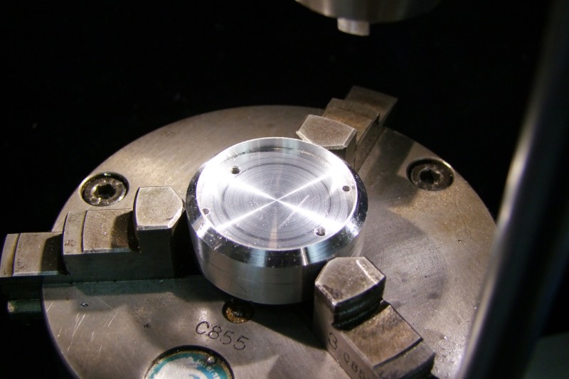
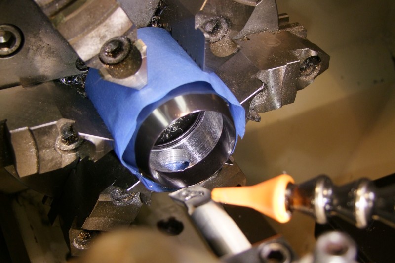
How often are you working on a part on the lathe, you need to cut it off to size, and when the part falls, it bounces, and gets damaged?

Sure, you can try something dangerous like having your hand close by to "catch" the part, but that is too risky, plus parting generates serious energy, and the cut-off piece might be "very" hot to catch anyway.

I have tried putting down a cleaning cloth, held in place by magnets, but the parts can still roll, bounce, etc..

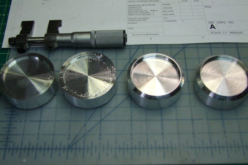
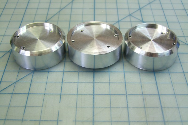
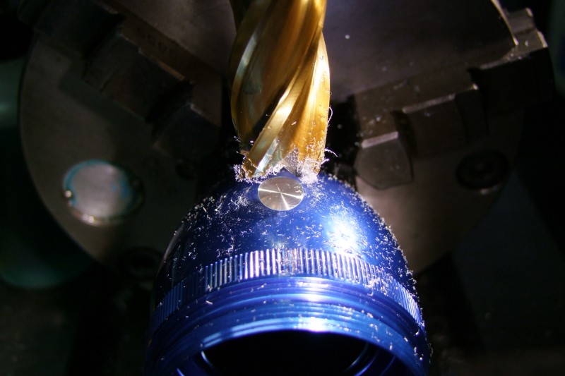
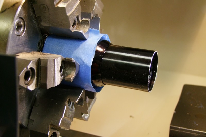
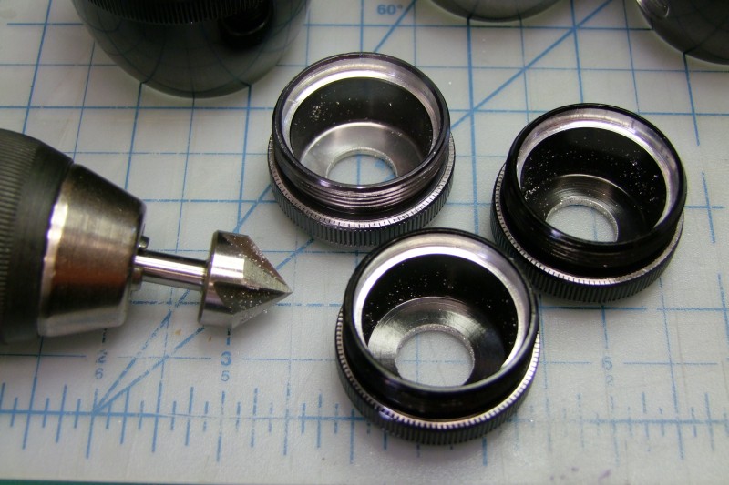
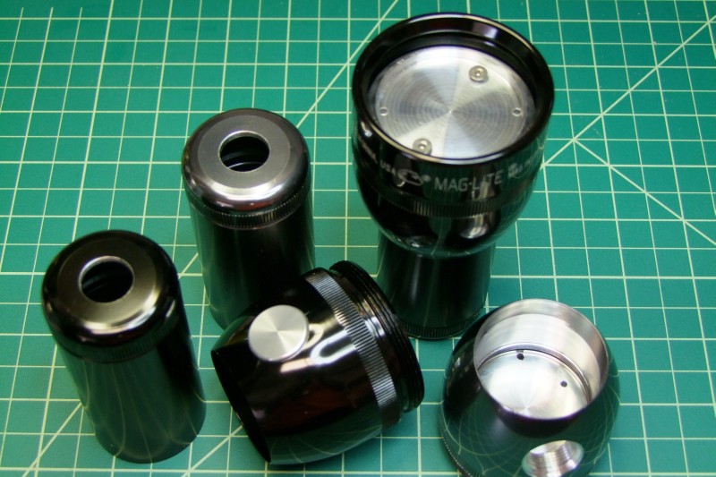
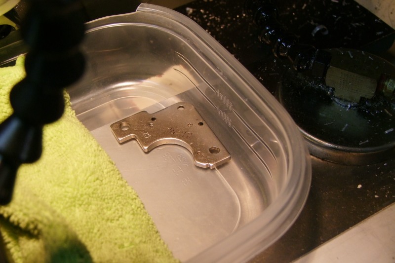
In fact, just today, I am working on some custom parts, and the 3rd part bounced "wrong" and got damaged:
DSCF9226.JPG


DSCF9227.JPG


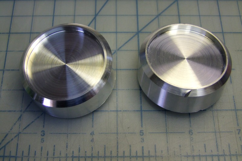
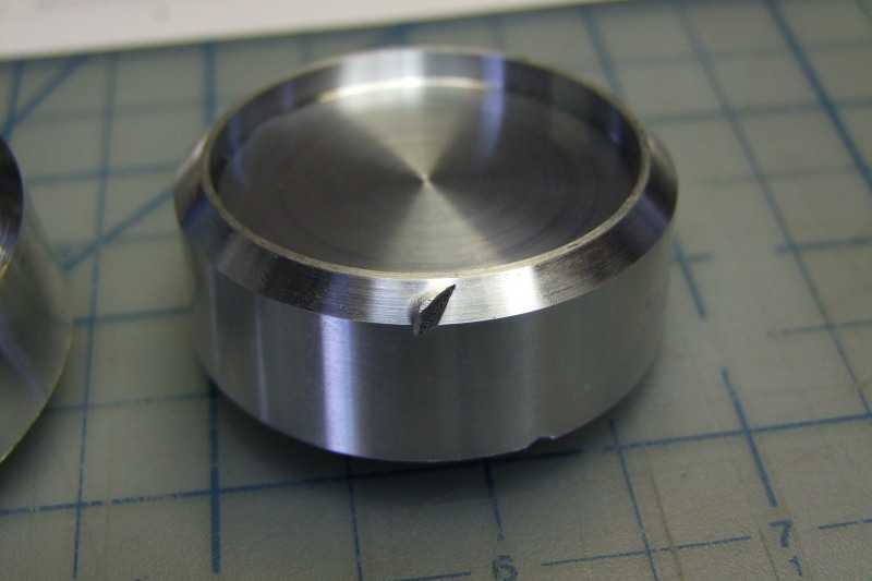
I must admit that it does not happen often, but when it does, like above, means starting all over .....

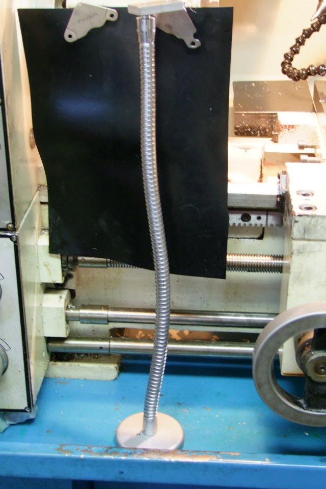
So, today I came up with the (soon to be patented!) "Cut-off parts catcher system" (I need to also try to trademark that!).

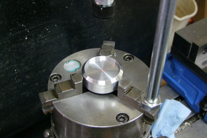
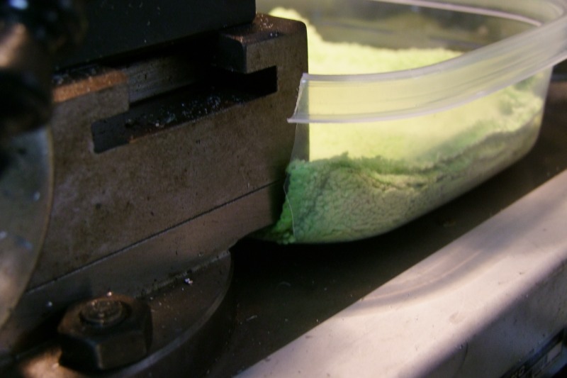
It is a very seriously looking, very complicated (and expensive to make!) "device":
DSCF9228.JPG


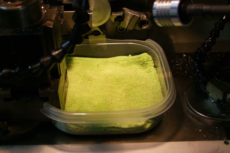
Completely manufactured in a state of the art CNC machine, and custom fitted to my own lathe:
DSCF9229.JPG


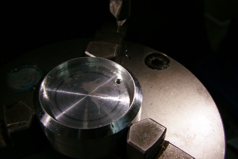
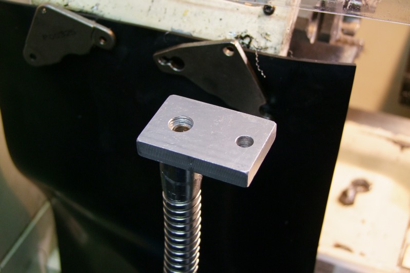
Totally adjustable on the distance to the chuck:
DSCF9230.JPG


DSCF9231.JPG


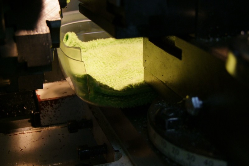
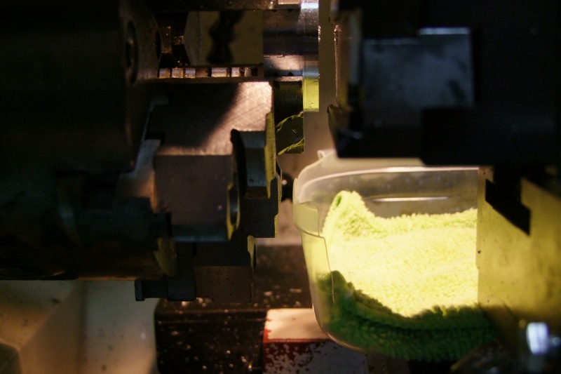
And it uses a super expensive, hard to get, space-age "retention device":
DSCF9232.JPG


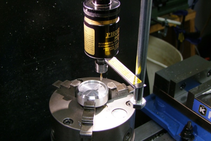
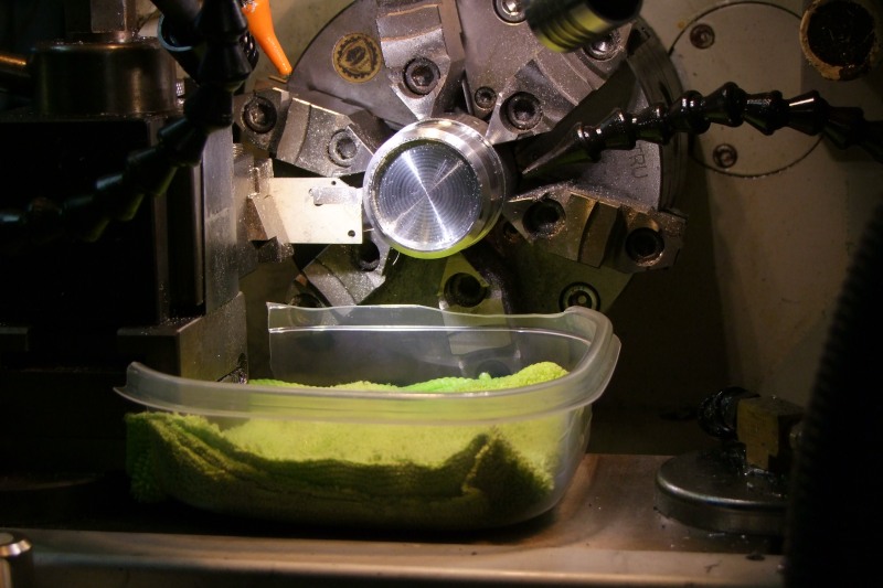
Here is the complete "system" in place:
DSCF9233.JPG


And here is a short movie showing my new "invention" in operation:
http://youtu.be/5DxZ1N-AoAw

Lathe = Precision Mathews 12x36
Spindle RPM = 900
Part diameter = 1.90"
Lubrication = Accu-Lube (near-dry system), two nozzles, with LB2000 cutting fluid
Cutting Tool = Iscar Do-Grip, 26mm blade, 0.123" insert width
Camera = FujiFilm S100FS


I can of course license it to anyone for a fee of "One million dollars !!!!" (quoting Dr. Evil from Austin Powers)

Will
 

KC2IXE

Flashaholic*
Joined
Apr 21, 2001
Messages
2,237
Location
New York City
I claim prior art with my self sealing cardboard version - when done, the cover closes, storing the trapped part
 

will

Flashlight Enthusiast
Joined
Apr 14, 2004
Messages
2,597
I would suggest one change. Put a paper towel in the bottom instead of a cloth towel. I have had ( rarely ) the cutoff chip pick up chips that are in the lathe bed. Picking up the cloth would really make a mess. Paper towels would just tend to rip to shreds.

( My fee for engineering changes is 1.1 million )
 

wquiles

Flashaholic
Joined
Jan 10, 2005
Messages
8,459
Location
Texas, USA, Earth
Ummmm... A little extra time today? haha!! I wish you the best of luck with your new parts catcher invention. :)
Just having some fun at my own expense.


I claim prior art with my self sealing cardboard version - when done, the cover closes, storing the trapped part
Ahh man, and I was "sure" this was 100% original. There goes the license fees down the drain .....


I would suggest one change. Put a paper towel in the bottom instead of a cloth towel. I have had ( rarely ) the cutoff chip pick up chips that are in the lathe bed. Picking up the cloth would really make a mess. Paper towels would just tend to rip to shreds.

( My fee for engineering changes is 1.1 million )
Thanks for the tip - makes sense.

And the check for the fees in in the mail ..... :devil:

Will
 
Last edited:

Mirage_Man

Flashlight Enthusiast
Joined
Apr 2, 2006
Messages
2,168
Location
Florida
Great idea Will. I've ruined my fair share of parts while parting off and heraing that dreaded thunk of the part falling into the chip pan after bouncing off some other part of the lathe.

One question though... why such a slow in feed speed?
 

wquiles

Flashaholic
Joined
Jan 10, 2005
Messages
8,459
Location
Texas, USA, Earth
Great idea Will. I've ruined my fair share of parts while parting off and heraing that dreaded thunk of the part falling into the chip pan after bouncing off some other part of the lathe.
Hopefully I will ruin less parts from now on. The 3x custom heatsinks are not clean yet in this picture, and I still have to do the drill/tap operations, but here on the left are the 3x "good" ones (the customer gave me a properly done dimensioned drawing with tolerances, side views, etc. - I wish all customers were so detailed):
DSCF9244.JPG


One question though... why such a slow in feed speed?
I am parting a nearly 2" part, with a relatively wide insert (0.123"), so I am taking my time - I usually get in trouble when I try to do cutt-offs too fast. When I look at the video myself, it does look awfully slower than when I am looking at the cut in real time.

Will
 
Last edited:

Mirage_Man

Flashlight Enthusiast
Joined
Apr 2, 2006
Messages
2,168
Location
Florida
I part ti with a.125" insert at 340rpm with a feed around .005"-.007" per revolution....dry. :devil:
 

wquiles

Flashaholic
Joined
Jan 10, 2005
Messages
8,459
Location
Texas, USA, Earth
I part ti with a.125" insert at 340rpm with a feed around .005"-.007" per revolution....dry. :devil:

I am not ready to try that :)


I got the 3x custom heatsinks finished today. First center them in the Yuasa:
DSCF9246.JPG


Drill and chamfer - get ready for threading:
DSCF9247.JPG


Tap the two holes (180deg apart):
DSCF9248.JPG


The two extra holes near the inside edge are for the LED wires:
DSCF9249.JPG


All 3x ready to go :)
DSCF9252.JPG


Will
 

vestureofblood

Flashlight Enthusiast
Joined
Jun 19, 2008
Messages
3,211
Location
Missouri
LOL! I have a similar piece of technology. Mine is a small flat rate box with the top torn off and a wash cloth in it. Sits real nice next to the edge of the compound.
 

wquiles

Flashaholic
Joined
Jan 10, 2005
Messages
8,459
Location
Texas, USA, Earth
What are these for Will? Nice!
It is for a customer :D


I'll have to make a video clip some time. It's no big deal really.
I made this small little "adapter" at the end of a flexible mag-base arm to allow me much easier/flexible video capability. This is what I used to do the short video on the very first post:
DSCF9235.JPG


DSCF9236.JPG


LOL! I have a similar piece of technology. Mine is a small flat rate box with the top torn off and a wash cloth in it. Sits real nice next to the edge of the compound.
Yes, yes, I know. I am way late with my "invention" :(
 

wquiles

Flashaholic
Joined
Jan 10, 2005
Messages
8,459
Location
Texas, USA, Earth
A few more updates ...

The biggest challenge with the holes for the piezo switch are that you need to find the center in a curved surface, and you have to find the angle that will put the switch perpendicular to the head. I used this to center front/back (y axis) to less than 0.0005":
DSCF9309.JPG


Here is how you know you got good centering - look how even the mill is cutting on both sides:
DSCF9311.JPG


And then I did a couple of test cuts and adjusted the Yuasa until I was pretty much dead center on the angle. Here i am probably within a 1/10 of a degree off - that was the closest I was able to do it:
DSCF9333.JPG


How close was "close enough"? I will let this picture do the talking:
DSCF9337.JPG


Here is a video of the threading operation on the knee mill:
Hole = 15mm
Angle on Yuasa = approx -12 deg
RPM = 200

http://youtu.be/WnuzXg7JbLg


Will
 
Last edited:

wquiles

Flashaholic
Joined
Jan 10, 2005
Messages
8,459
Location
Texas, USA, Earth
I finished the last few operations this week. Partially remove threads on head:
DSCF9339.JPG

DSCF9340.JPG


Drill and chamfer tailcaps for cable glands:
DSCF9342.JPG


DSCF9343.JPG


All parts done and ready:
DSCF9345.JPG


Will
 
Top