
Epsilon
Enlightened
This topic describes two builds of the last few months of which I hadn't done a write-up. I think the information is very usefull for new modders so better late than never ") .
.
Enjoy :twothumbs
Mag2D Rebel XM-L U2
This build I made in september 2012 for my dads birthday, but never did a write-up of the build. It still is very relevant, so I decided to make one
Parts:
- Maglite 2D Rebel Gunmetal grey
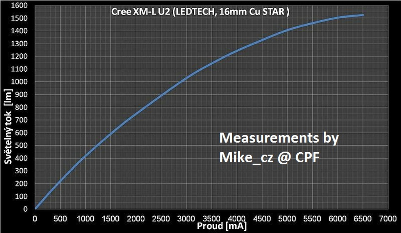
- XM-L U2 on Copper Led-Tech.de PCB (look for the graph below for performance figures).
- TaskLed H6Flex driver for the much needed power supply.
- H22A P7 flat top heatsink
- M3 set-screw
- Glass lens
Almost all the pictures are clickable
This graph is from a CPF user (added the credits) very well done. His topic here
Preparing the switch:


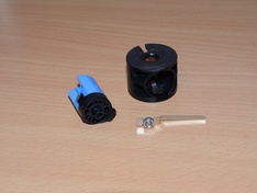
Momentary switch mod
The H6Flex needs a momentary switch to operate, so did the needed modifications. There are lots of guides around, so I will not go into too much detail here.
Exploded view:

Note the 4th part from the left. This normally has teeth, which I removed. The 5th part from the left (2nd from the right) still has it's teeth, which is fine. A lot of guides say that they need to be removed: The don't need to be removed (it's fine if you do though).

The bottom lip is cut, this is the part that normally touches the positive terminal of the switch.
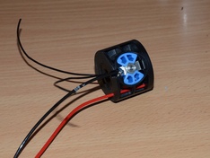
Soldered the wires:


On this picture, it is pretty clear how the momentary switch works. When pressed, the two contacts are connected by the metal (silver I think actually) ring. The removal of the teeth as depicted in the above pictures, stops the switch from sticking in the "ON" position.
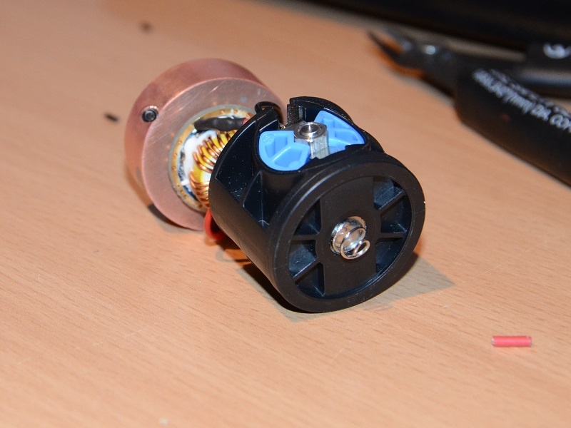
Putting the button back together and funnel the wires:

Reassembling the switch and bypassing the positive terminal


On to the heatsink and driver
Filed the rim off the heatsink:

I cut a piece of aluminium to free up the solder points of the driver. This piece of aluminium is thermal-taped to the bottom of the driver.


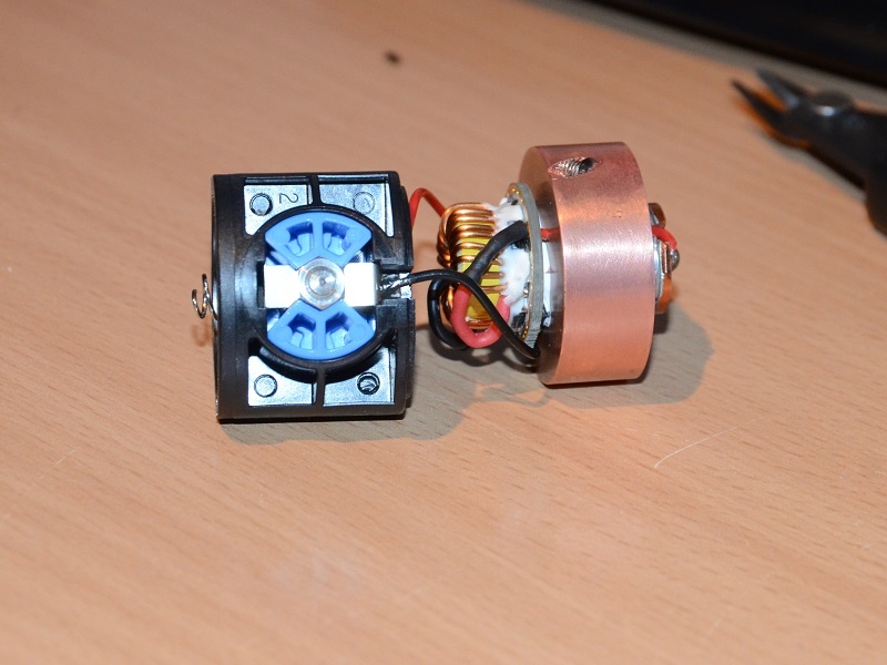
Soldered to the driver to the switch assembly:


Preparing the heatsink:
Drilled and tapped a hole for the Set-screw:


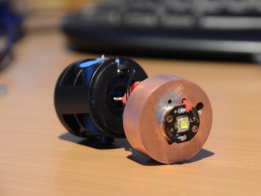
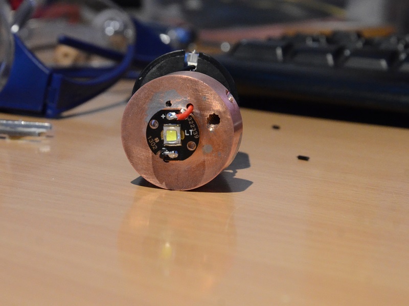
The LED:


Glued with AS adhesive:

Not shown: The LED PCB basis is lapped with 600grid sandpaper for a good bond.
Cutting the reflector
The reflector cut for this build is very easy to do right!
Cut only the neck, leave the rest intact! When pressed fully on the PCB, you will have a perfect focussed hotspot!


Not shown: Thermal-taping the driver to the heatsink.
Apply some Arctic alumina thermal compound on the sides of the heatsink and on the neck. Screw the set-screw tight and the head of the Maglite back on the neck. The thermal compound on the neck ensures heat transfer to the heat as well as the body.


Finished:

I measured the temperatus @ 5amps (not holding the light, no airflow, just lying flat on the table:
So the light can certainly be run continously when held or not. It will get unconfortably warm when not held though .
Maglite 2D XM-L2 U2 Build
About a month back, I decided to make a similar build for myself. I kept grabbing my dads light to compare with other lights.
I had a couple of Copper heatsinks to fit in a MagD, so I used one for this build instead of the H22A aluminium heatsink.
The setup is basically the same, but the parts are all different:
- Copper homemade heatsink
- Lck-Led 5A STT 4 mode driver (actually it does 4.5A, which is fine).
- XM-L2 U2 on Copper PCB (Led-tech.de)
- No momentary mod this time
- Blue Mag2D rebel.
- M4 (4mm) set-screw instead of M3 (3mm).
- Glass lens
Some pics of the build:
The set-screw tightly pushes the heatsink against the Maglite neck. Even with minimal tollerances, there will always be a gap, the setscrew ensures at least one place of good contact area.
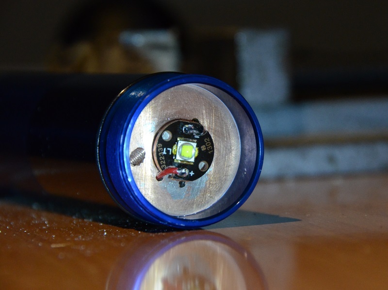
And the finished project:
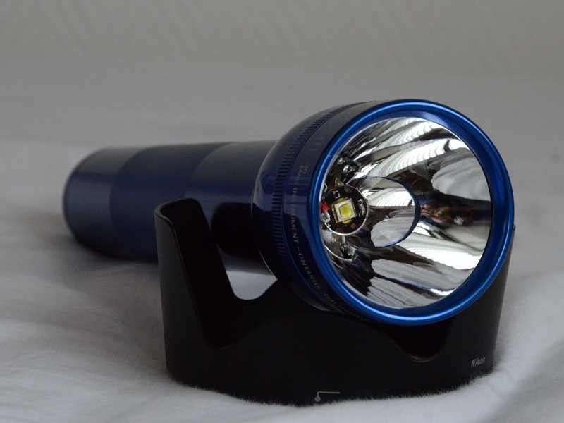
Beamshots
And to compare, a few beamshots of the lights side by side:
setup:
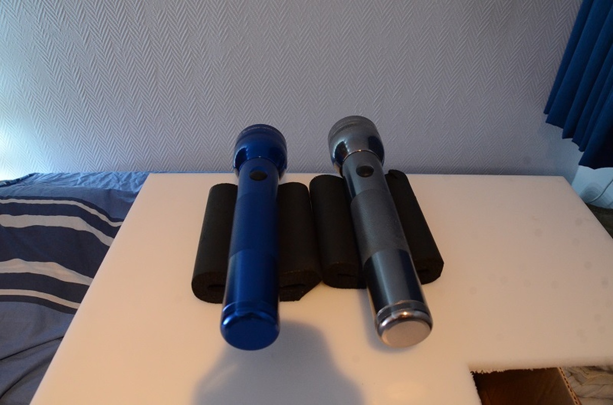
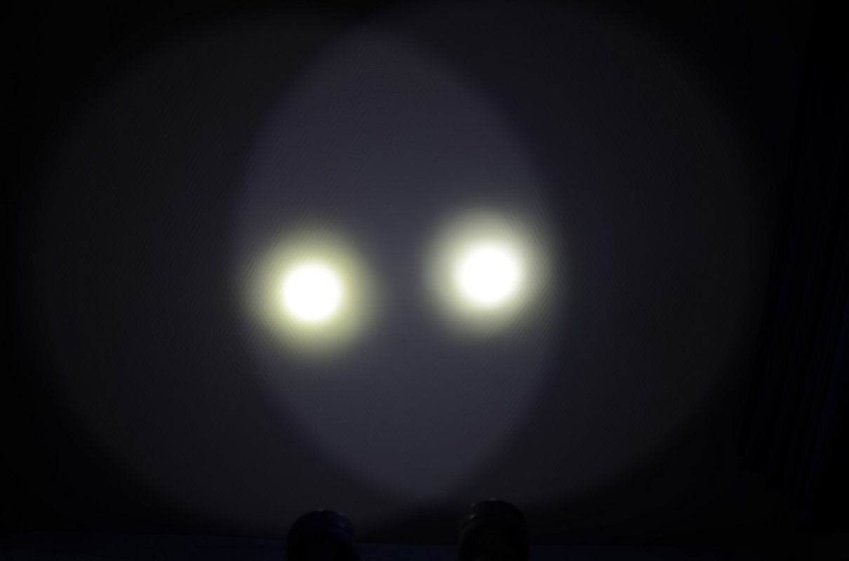
Left = XM-L2 U2 @ 4.5A Right = XM-L U2 @ 5A
1/6400sec:

1/200sec
At these drivecurrents the lights are very comparable. Of course, the TaskLed driver is the one I would prefer any day because of the extra functionalities. But the Lck-Led driver I had left over for a build that didn't pull through and it does actually really well.
.Enjoy :twothumbs
Mag2D Rebel XM-L U2
This build I made in september 2012 for my dads birthday
, but never did a write-up of the build. It still is very relevant, so I decided to make one Parts:
- Maglite 2D Rebel Gunmetal grey
- XM-L U2 on Copper Led-Tech.de PCB (look for the graph below for performance figures).
- TaskLed H6Flex driver for the much needed power supply
.- H22A P7 flat top heatsink
- M3 set-screw
- Glass lens
Almost all the pictures are clickable
This graph is from a CPF user (added the credits) very well done
. His topic here
Preparing the switch:


Momentary switch mod
The H6Flex needs a momentary switch to operate, so did the needed modifications. There are lots of guides around, so I will not go into too much detail here
.Exploded view:

Note the 4th part from the left. This normally has teeth, which I removed. The 5th part from the left (2nd from the right) still has it's teeth, which is fine. A lot of guides say that they need to be removed: The don't need to be removed (it's fine if you do though).

The bottom lip is cut, this is the part that normally touches the positive terminal of the switch.
Soldered the wires:


On this picture, it is pretty clear how the momentary switch works. When pressed, the two contacts are connected by the metal (silver I think actually) ring. The removal of the teeth as depicted in the above pictures, stops the switch from sticking in the "ON" position.
Putting the button back together and funnel the wires:

Reassembling the switch and bypassing the positive terminal


On to the heatsink and driver
Filed the rim off the heatsink:

I cut a piece of aluminium to free up the solder points of the driver. This piece of aluminium is thermal-taped to the bottom of the driver.


Soldered to the driver to the switch assembly:


Preparing the heatsink:
Drilled and tapped a hole for the Set-screw:


The LED:


Glued with AS adhesive:

Not shown: The LED PCB basis is lapped with 600grid sandpaper for a good bond.
Cutting the reflector
The reflector cut for this build is very easy to do right!
Cut only the neck, leave the rest intact! When pressed fully on the PCB, you will have a perfect focussed hotspot!


Not shown: Thermal-taping the driver to the heatsink.
Apply some Arctic alumina thermal compound on the sides of the heatsink and on the neck. Screw the set-screw tight and the head of the Maglite back on the neck. The thermal compound on the neck ensures heat transfer to the heat as well as the body.


Finished:

I measured the temperatus @ 5amps (not holding the light, no airflow, just lying flat on the table:
Code:
@5000mA
sec	temp (DegC)
  0	24.2
 30	25.4
 60	27.0
 90	28.4
120	29.7
150	30.8
180	32.1
210	33.2
240	34.2
270	34.9
300	35.8		delta 11.6
330
360	37.3
390	38.5
420	39.1
450	39.7
480	40.2
510	41.0
540	41.4
570	41.9
600 42.6 delta 18.4Maglite 2D XM-L2 U2 Build
About a month back, I decided to make a similar build for myself
. I kept grabbing my dads light to compare with other lights.I had a couple of Copper heatsinks to fit in a MagD, so I used one for this build instead of the H22A aluminium heatsink.
The setup is basically the same, but the parts are all different:
- Copper homemade heatsink
- Lck-Led 5A STT 4 mode driver (actually it does 4.5A, which is fine).
- XM-L2 U2 on Copper PCB (Led-tech.de)
- No momentary mod this time
- Blue Mag2D rebel.
- M4 (4mm) set-screw instead of M3 (3mm).
- Glass lens
Some pics of the build:
The set-screw tightly pushes the heatsink against the Maglite neck. Even with minimal tollerances, there will always be a gap, the setscrew ensures at least one place of good contact area.
And the finished project:
Beamshots
And to compare, a few beamshots of the lights side by side:
setup:
Left = XM-L2 U2 @ 4.5A Right = XM-L U2 @ 5A
1/6400sec:
1/200sec
At these drivecurrents the lights are very comparable. Of course, the TaskLed driver is the one I would prefer any day because of the extra functionalities. But the Lck-Led driver I had left over for a build that didn't pull through and it does actually really well.
Last edited:

