find_bruce
Newly Enlightened
- Joined
- May 5, 2011
- Messages
- 84
My commute is 10km each way in the city of Sydney, Australia. For the last 2 years I have been using various li-ion powered lights, both ubiquitous Chinese bike lights, flashlights & a triple XP-G from lux-rc. I have been particularly happy with my taillight, a red XP-C flashlight driven at 700 mA. It was so bright I added a deodorant ball as a diffuser

Like many regular commuters though I started to get bored with remembering to recharge the batteries & have been toying with the idea of switching to dynamo lights. Of course this involved much reading here and elsewhere. Sure I could simply go out and buy all the bits, but I decided to assemble as much of it as I could by myself.
This is very much a work in progress, but I thought others might benefit from seeing what I have done, especially the mistakes I have made.
Dynamo This was the easy bit. Having heard good reviews about the dyno hubs from Shutter Precision I chose a PD-8. With Roger Musson's wheelbuilding book the wheel build was straightforward, apart from discovering I had entered the wrong figures into the spoke calculator & had to order new spokes.
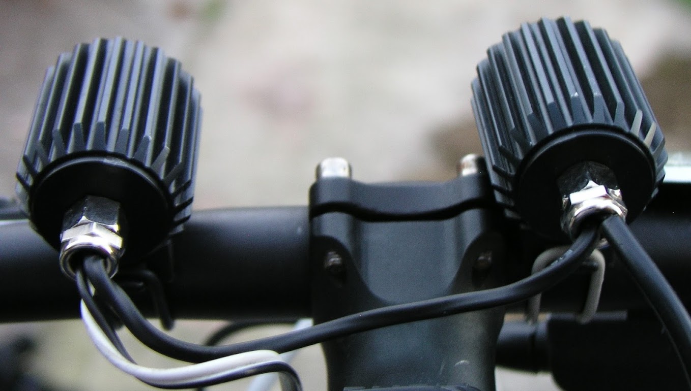
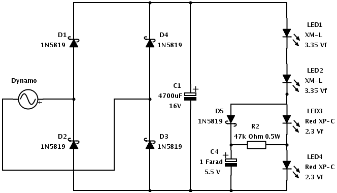
Lights like pretty much everyone considering building dynamo powered lights, I started with Martin's dynamo circuits. Without going into the tortured decision making process I initially settled on a 3 led set up with 2 x xml up front and a red xpc for the taillight. Running at 0.5A the cooling requirements are not high, but I happened to have 3 easy2led housings, so I used those. The only difference to the standard set-up is that I decided to run the taillight in series. My post-decision rationalisation is that I didn't want to reduce the power available to the front leds, I wanted the red led to operate at full power & the red led would comfortably handle the 0.5A of a dynamo.
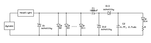
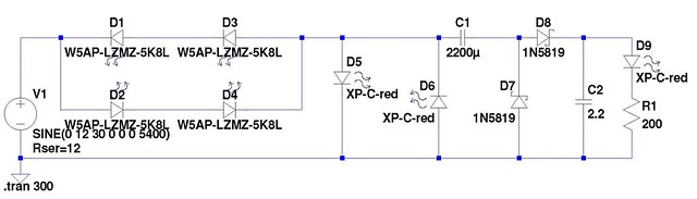
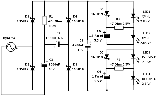
Standlights however had me stumped & I had all but given up. Then I read a couple of posts by SteveK the first of which got me reading the standlight thread & the second posted a simple standlight circuit. When I read this post by FrontRanger & went back to SteveK's circuit, I slowly started to understand. Based on these, I came up with this circuit.

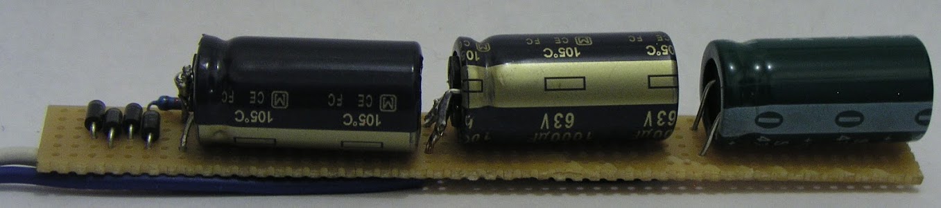
I didn't have all the necessary bits, but what I built over the weekend was
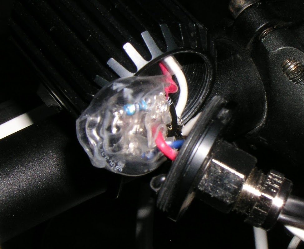
To fit 2 red LEDs in 1 easy2led housing, I took some brave pills & then picked up my aviation snips & simply cut off the "excess" aluminium star. Forgive the dodgy phone pic, but this was the result.
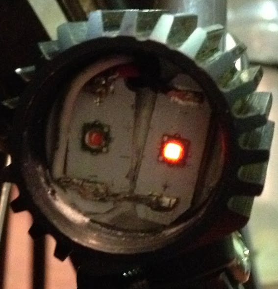
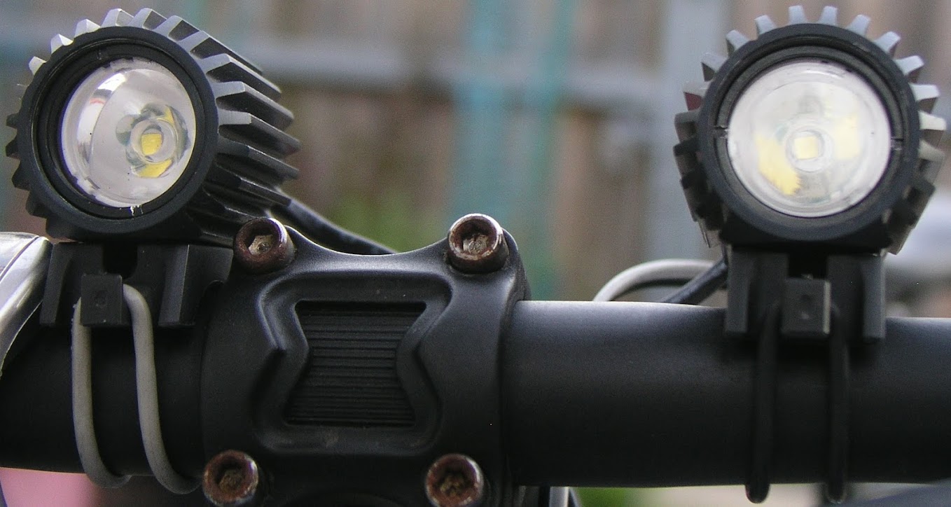
It works pretty much as you would expect. One XM-L uses a 30° optic while the other uses a 15° optic, giving a nice balance of flood & throw. With no doubling circuit & no tuning capacitors it doesn't emit much light below 10 km/h, but I don't spend much time at that speed & I have a battery powered helmet light in any event.
Znomit said "500mA through two red LEDs is crazy bright" & I can happily confirm that he is 100% correct. With my deodorant ball diffuser I can tell that the rear is working because of the red glow over the entire rear of the bike. I will see if I can come up with a safe and interesting way to take a picture of the rear light.
The observant will note that I have added one little letter to R2. Yep, I accidentally picked up a 47k ohm resistor instead of 47 ohm resistor . The result, as you would expect, is that as a standlight, LED4 emits a very dull glow, my maths suggests something like 0.00004 amps. On the plus side however that dull glow continues for a very long time, more than 10 hours – the above pic was taken about 6 hours after I stopped riding.
My mistake did however get me thinking about how the circuit worked & how the value of R2 affects it. After charging C4, I bypassed R2 with the result that LED4 glowed nice & bright. Of course when I spun the wheel, as you would expect LED3 did not light up & C4 would only charge to the Vf of LED4, something around 2.3v.
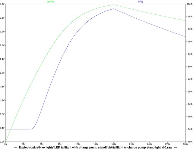
If I have it correct in my head now, what you are trying to achieve is a balance. As the resistance of R2 increases, when the dynamo is operating you will get a greater current flowing to LED3 and a higher charge to C4, however this will be at the expense of the current to LED4 when the dynamo is not operating. Both the higher charge of C4 and the lower standlight current to LED4 increases the length of time the standlight functions.
Hopefully over the weekend I will get some time to experiment with some different resistors 23.5, 47 & 94 ohm, to see what affect it has on the current at L4 and the useful standlight time.
The other thing I have noticed is that 2.5v supercaps are easy to come by and cheap and the Vf of red XP-C leds is 2.3V, so I have ordered a 2.5v 3.3F supercap to see how that performs as a standlight.
I look forward to your comments.
Like many regular commuters though I started to get bored with remembering to recharge the batteries & have been toying with the idea of switching to dynamo lights. Of course this involved much reading here and elsewhere. Sure I could simply go out and buy all the bits, but I decided to assemble as much of it as I could by myself.
This is very much a work in progress, but I thought others might benefit from seeing what I have done, especially the mistakes I have made.
Dynamo This was the easy bit. Having heard good reviews about the dyno hubs from Shutter Precision I chose a PD-8. With Roger Musson's wheelbuilding book the wheel build was straightforward, apart from discovering I had entered the wrong figures into the spoke calculator & had to order new spokes.
Lights like pretty much everyone considering building dynamo powered lights, I started with Martin's dynamo circuits. Without going into the tortured decision making process I initially settled on a 3 led set up with 2 x xml up front and a red xpc for the taillight. Running at 0.5A the cooling requirements are not high, but I happened to have 3 easy2led housings, so I used those. The only difference to the standard set-up is that I decided to run the taillight in series. My post-decision rationalisation is that I didn't want to reduce the power available to the front leds, I wanted the red led to operate at full power & the red led would comfortably handle the 0.5A of a dynamo.
Standlights however had me stumped & I had all but given up. Then I read a couple of posts by SteveK the first of which got me reading the standlight thread & the second posted a simple standlight circuit. When I read this post by FrontRanger & went back to SteveK's circuit, I slowly started to understand. Based on these, I came up with this circuit.
I didn't have all the necessary bits, but what I built over the weekend was
To fit 2 red LEDs in 1 easy2led housing, I took some brave pills & then picked up my aviation snips & simply cut off the "excess" aluminium star. Forgive the dodgy phone pic, but this was the result.
It works pretty much as you would expect. One XM-L uses a 30° optic while the other uses a 15° optic, giving a nice balance of flood & throw. With no doubling circuit & no tuning capacitors it doesn't emit much light below 10 km/h, but I don't spend much time at that speed & I have a battery powered helmet light in any event.
Znomit said "500mA through two red LEDs is crazy bright" & I can happily confirm that he is 100% correct. With my deodorant ball diffuser I can tell that the rear is working because of the red glow over the entire rear of the bike. I will see if I can come up with a safe and interesting way to take a picture of the rear light.
The observant will note that I have added one little letter to R2. Yep, I accidentally picked up a 47k ohm resistor instead of 47 ohm resistor
. The result, as you would expect, is that as a standlight, LED4 emits a very dull glow, my maths suggests something like 0.00004 amps. On the plus side however that dull glow continues for a very long time, more than 10 hours – the above pic was taken about 6 hours after I stopped riding.My mistake did however get me thinking about how the circuit worked & how the value of R2 affects it. After charging C4, I bypassed R2 with the result that LED4 glowed nice & bright. Of course when I spun the wheel, as you would expect LED3 did not light up & C4 would only charge to the Vf of LED4, something around 2.3v.
If I have it correct in my head now, what you are trying to achieve is a balance. As the resistance of R2 increases, when the dynamo is operating you will get a greater current flowing to LED3 and a higher charge to C4, however this will be at the expense of the current to LED4 when the dynamo is not operating. Both the higher charge of C4 and the lower standlight current to LED4 increases the length of time the standlight functions.
Hopefully over the weekend I will get some time to experiment with some different resistors 23.5, 47 & 94 ohm, to see what affect it has on the current at L4 and the useful standlight time.
The other thing I have noticed is that 2.5v supercaps are easy to come by and cheap and the Vf of red XP-C leds is 2.3V, so I have ordered a 2.5v 3.3F supercap to see how that performs as a standlight.
I look forward to your comments.