papershredder
Newly Enlightened
- Joined
- May 31, 2013
- Messages
- 132
I have another thread where I started out putting a ~3000K high CRI Cree into a Preon P2. However, I wanted to provide a picture tutorial on how to swap emitters on this light, thus a new thread to get that info to the top. I changed my technique slightly, which makes this much easier. That's the blowtorch.
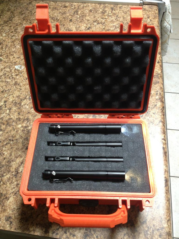
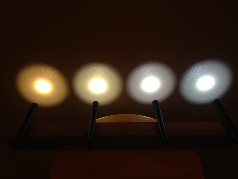
At the end, I'll show off my collection of ~3000K, 4000K, 5000K and 6300K Preon P2's. Old thread is here: http://www.candlepowerforums.com/vb...Preon-P2-cool-white-to-warm-white-mod-(2900k)
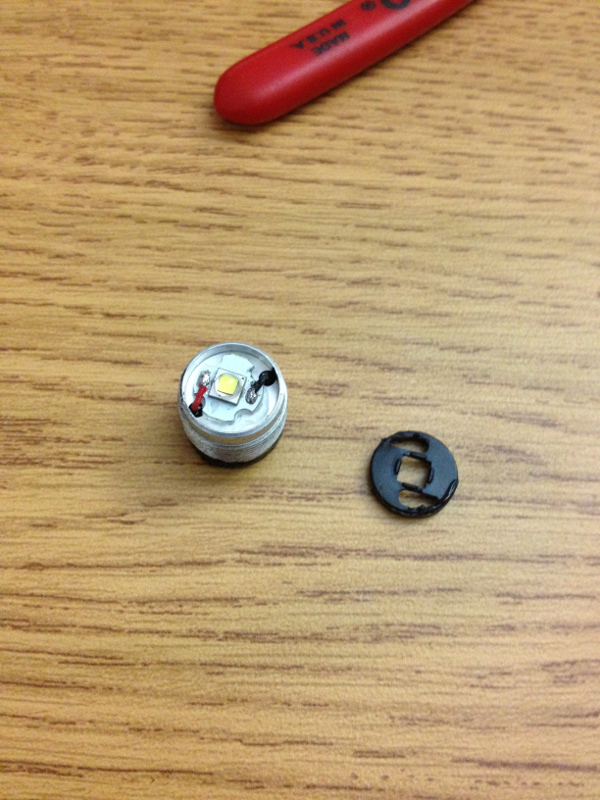
This is the Preon head. See those two holes in the PCB? Those are important for later.
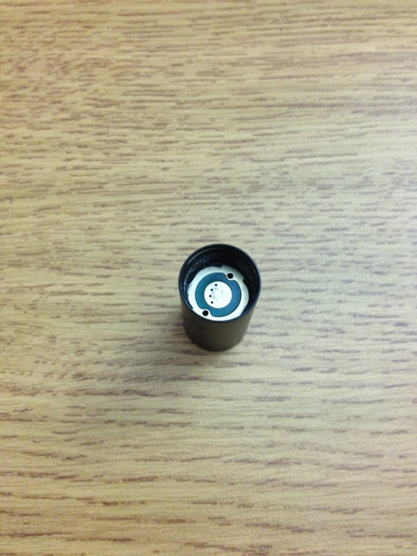
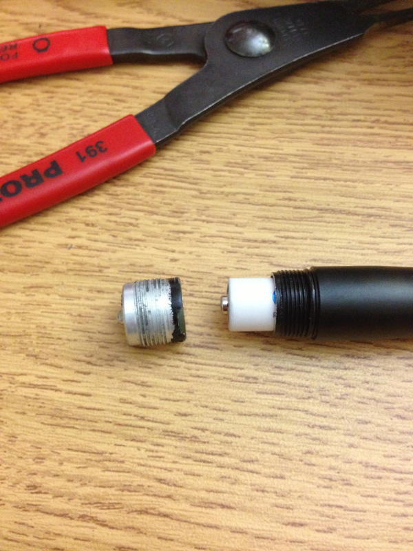
There is a "pill" inside the head that we have to get out.
Basically the whole assembly is an anodized aluminum body. Inside is an o-ring for the lens, the lens, the reflector, and the pill.
The pill contains two PCB's. One of which is glued in, and one side of that is where the battery positive terminal and rest of the body touch.
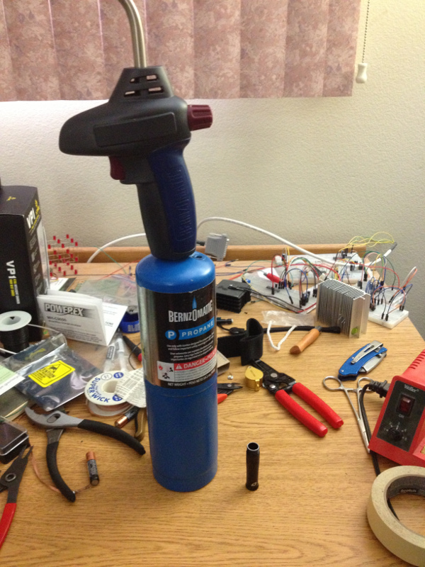
To get the pill out, we have to break thread lock gunk.
Get your blowtorch out.
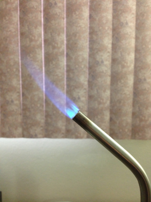
Gentle flame. This is probably the trickiest part. Not enough heat and the pill won't budge. Too much and you'll start to burn up the insides.
Start out with short durations of heat and work your way up as necessary. I was probably in the flame for two seconds while rotating the head.
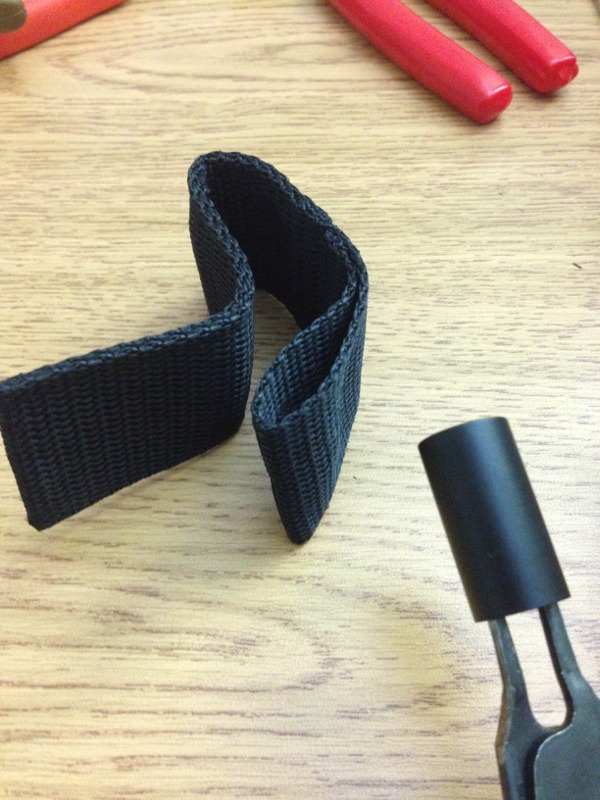
While that head is still warm, get your retaining ring pliers in there. That piece of nylon is for me to grip the head without burning my hand. Nylon melts by the way...
Updated August 11, 2013.
Try working with a little bit of heat. I've had a variety of heads and experiences. One I could just unscrew from the factory.
Another came out with some heat. I had one pill that I could simply not remove.
More often than not, I break the glue holding the PCB where the ring pliers insert. This is a great nuisance. I wish I had some photos for you, but I'll explain the extraction at that point:
Notes:
Once you get it out, cover the head so no dust gets on the lens and reflector.
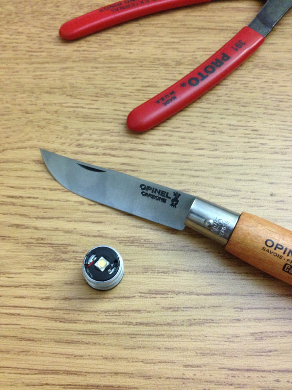
Here's the pill:

I recommend giving that pill a quick test to make sure your machinations so far have not toasted it:
There is a plastic piece that centers and retains the PCB. Pop that out. I used a small knife to prise it out by putting the blade tip inside one of those two holes and levering it out.
Desolder the PCB. Don't cut those wires, you'll need the length.
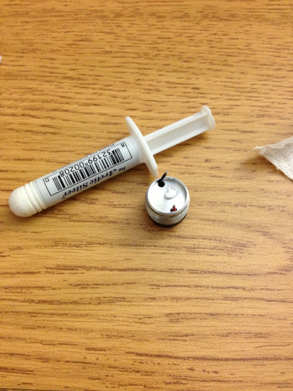
I cleaned up and put some fresh thermal paste down. This is optional.
Reassemble the pill by putting down your new emitter on a PCB. This can be on a new small PCB. (8mm works.) Re-solder the wires.
Avoid too much solder, and try and keep it on the periphery so that the retaing ring goes back on well. It has to sink down the sides of that XP-G package.
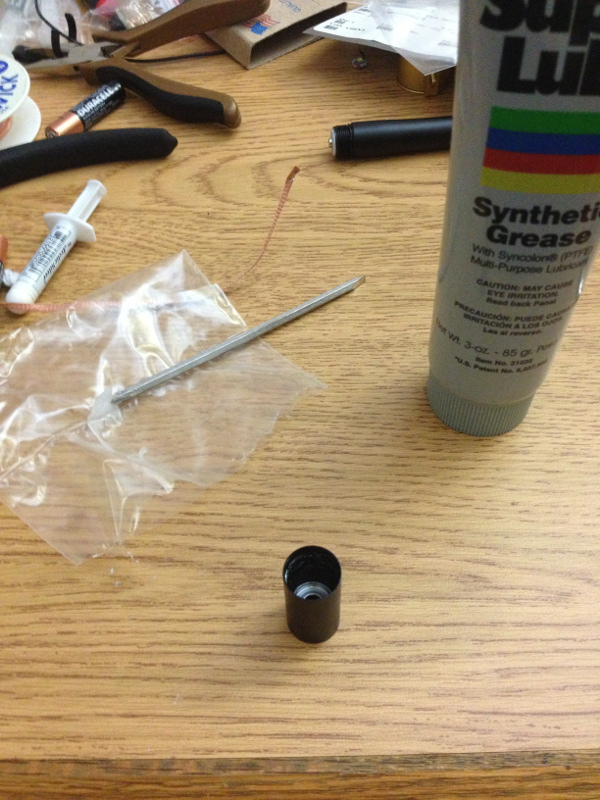
Once the pill is back in order, a little lube never hurts, well, okay, maybe if you get it in your eye.
Now, for some results:
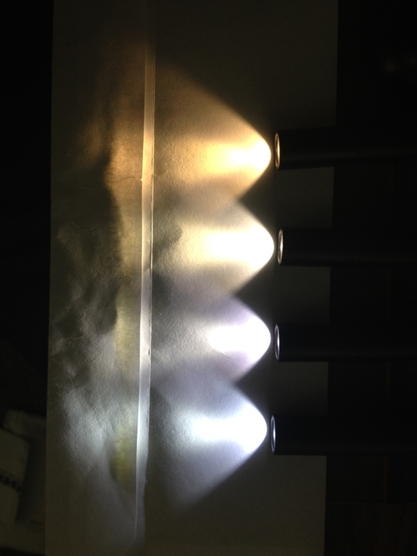
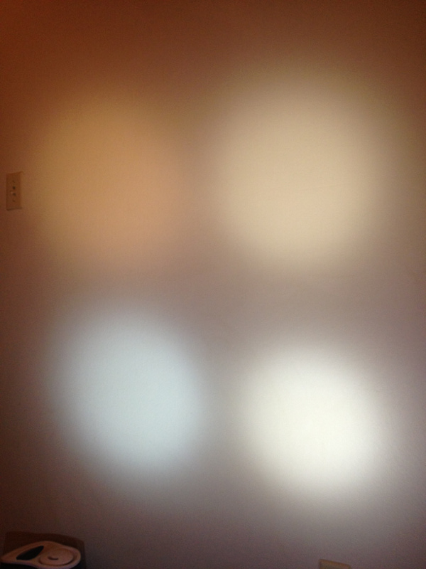
They did an awful job getting similar tints into this tiny monster! I'm sending it back! =)
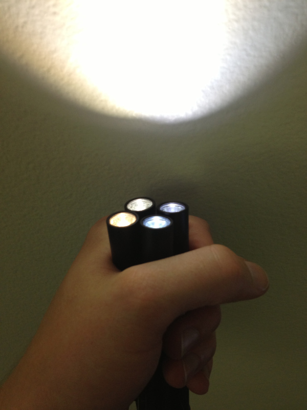
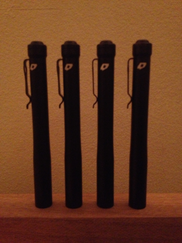
The gang, hanging out.
Enjoy!
At the end, I'll show off my collection of ~3000K, 4000K, 5000K and 6300K Preon P2's. Old thread is here: http://www.candlepowerforums.com/vb...Preon-P2-cool-white-to-warm-white-mod-(2900k)
This is the Preon head. See those two holes in the PCB? Those are important for later.
There is a "pill" inside the head that we have to get out.
Basically the whole assembly is an anodized aluminum body. Inside is an o-ring for the lens, the lens, the reflector, and the pill.
The pill contains two PCB's. One of which is glued in, and one side of that is where the battery positive terminal and rest of the body touch.
To get the pill out, we have to break thread lock gunk.
Get your blowtorch out.
Gentle flame. This is probably the trickiest part. Not enough heat and the pill won't budge. Too much and you'll start to burn up the insides.
Start out with short durations of heat and work your way up as necessary. I was probably in the flame for two seconds while rotating the head.
While that head is still warm, get your retaining ring pliers in there. That piece of nylon is for me to grip the head without burning my hand. Nylon melts by the way...
Updated August 11, 2013.
Try working with a little bit of heat. I've had a variety of heads and experiences. One I could just unscrew from the factory.
Another came out with some heat. I had one pill that I could simply not remove.
More often than not, I break the glue holding the PCB where the ring pliers insert. This is a great nuisance. I wish I had some photos for you, but I'll explain the extraction at that point:
1. Gently pull the first PCB out, it will be attached via 3 wires. Unsolder these.
- B+ goes to the secondary PCB via a red wire. That is soldered next to the inductor.
- B- goes to the secondary PCB via a black wire. That is soldered to the non-striped end of that yellow tantalum capacitor.
- The black wire from the SOT-23 goes to the back side of the secondary PCB. That terminates at the striped side of the yellow tantalum capacitor.
2. Loosen the secondary PCB. It may be held in by the "bloom" of the thread locker. No problem, get a implement in there and break the bloom bridging it to the pill.
3. Rotate the secondary PCB inside the pill. Use small snips to cut the wires going to the emitter. Red is positive, black is negative.
3. Rotate the secondary PCB inside the pill. Use small snips to cut the wires going to the emitter. Red is positive, black is negative.
[*=1]Red wire attaches near a 6 pin SOT-23.
[*=1]Black wire attaches to the 3 pin SOT-23.
4. Extract both PCB's.
5. Retaining ring pliers will fit into where the emitter wires are going. Get in there and twist! Make sure your pliers are not scratching up the threading on the head body. It's okay to slightly maul the pill innards.
6. Clean up. Get the remaining thread lock out. I like to screw and unscrew the pill a few times in the head body to clean things up. Make sure any metal shavings are out.
7. Attach new leads to the secondary PCB for the emitter.
8. Re-attach the power leads between the two PCB's.
8. Reasseble the PCB's in the pill. Use a little craft glue to secure the first PCB into the pill.
Notes:
It'll be obvious which pin on the SOT-23's to wire to, they've got more solder.
You will need small angle snips to reach inside the head.
Get some nice grippy and thick rubber to hold the head in with normal pliers.
There is an o-ring in the head that'll likely stay in there. Be careful when you use solvents.
You will need small angle snips to reach inside the head.
Get some nice grippy and thick rubber to hold the head in with normal pliers.
There is an o-ring in the head that'll likely stay in there. Be careful when you use solvents.
Once you get it out, cover the head so no dust gets on the lens and reflector.
Here's the pill:
I recommend giving that pill a quick test to make sure your machinations so far have not toasted it:
There is a plastic piece that centers and retains the PCB. Pop that out. I used a small knife to prise it out by putting the blade tip inside one of those two holes and levering it out.
Desolder the PCB. Don't cut those wires, you'll need the length.
I cleaned up and put some fresh thermal paste down. This is optional.
Reassemble the pill by putting down your new emitter on a PCB. This can be on a new small PCB. (8mm works.) Re-solder the wires.
Avoid too much solder, and try and keep it on the periphery so that the retaing ring goes back on well. It has to sink down the sides of that XP-G package.
Once the pill is back in order, a little lube never hurts, well, okay, maybe if you get it in your eye.
Now, for some results:
They did an awful job getting similar tints into this tiny monster! I'm sending it back! =)
The gang, hanging out.
Enjoy!
Last edited: