Very very clean work! :naughty:
You are using an out of date browser. It may not display this or other websites correctly.
You should upgrade or use an alternative browser.
You should upgrade or use an alternative browser.
Homemade 15 emitter high-CRI Rebel LED flood light with red and cyan boost
- Thread starter jeffosborne
- Start date

MikeAusC
Enlightened
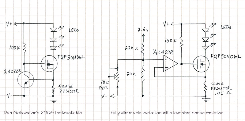
So what is the new formula for calculating what the CC will be with your new circuit, since if I use Dan's original one .5 / .05 = 10 amps!? Or am I missing something?
The answer is already in the post above with the photos -
- " My previous lights have used a small signal transistor across the sense resistor to regulate the MOSFET, which requires a .5 volt drop across the sense resistor – not very efficient. Here the small signal transistor is replaced with a comparator, so my sense resistor can be very low ohm - .05 ohm 1% is used. The voltage drop across this resistor is only .045 volts with the maximum 850ma current flow – much more efficient."
Mike
Ah so I was "missing" something LOL thanks Mike! :twothumbs
moviles
Enlightened
- Joined
- Feb 27, 2009
- Messages
- 456
really nice the low-ohm sense resistor version
Bimmerboy
Flashlight Enthusiast
WOW, Jeff! Your previous builds were already great, and they just keep getting better and better. Awesome power supply as well!
Fantastic work! :thumbsup:
Fantastic work! :thumbsup:
Ok I just tried to emulate the circuit above, but must have messed up something. I used a 10K ohm trim pot as that is the only 10K ohm pot I had on hand and instead of a lm239 I used a lm393 which is a dual comparator instead of the lm239's quad comparator. I was not able to get consistant results though. I couldn't get the current to go above about 600mA and the pot didn't really act very consistently. I have gone my wiring over and over but can't find an error "I will take a break and go over it again, as I have a habit of screwing stuff up and not seeing why". Has anyone tried to build Jeff's circuit and gotten it to work? Also Jeff I see in the diagram, above the voltage divider it says 2.5v.... I had just assumed that was a note about what the voltage divider was putting out into the + input of the comparator, is this correct, or am I again missing something?
Thanks!
EDIT
ok I just rebuilt the circuit using a lm2901 and a 5K ohm normal sized pot... this time the dimming seems to work much more linearly, except that it now instead of the current stopping at 600mA it goes all the way up to my power supplies limit of like 1.4 amps? Also everytime I touch the pot with my bare hands the led dims? LOL I should just stop for today and go watch some TV.
Last edited:
jeffosborne
Enlightened
Hey jason, it is good to hear you are trying out the circuit! My partial schematic's 2.5 volt reference is the output of a LM336-2.5 precision reference diode, that I include in most every design that requires a comparator.
As the supply voltage varies, whether that is a battery's declining voltage, or some ripple or noise in a AC-to-DC power supply, the voltage divider that your potentiometer is a part of is delivering that variance to the comparator, causing the drift and error you are seeing.
You need to include the super-simple LM336-2.5. It is a 3-pin device that looks like a small signal transistor. It connects to ground, and to the supply voltage through a 5K ohm resistor, and provides a very stable 2.5 volt output. Your potentiometer and resistor then provides a stable reference voltage to the comparator. The part is 31 cents each at Future Electronics.
The thermal portion of the circuit was asked about also. Really, I must get the whole schematic drawn out and share it. It is on my to-do list!
Cheers,
Jeff
Paul Baldwin
Enlightened
Very neat and tidy build that looks like it works well too ") I've another suggestion instead for drill bit lube with aluminium http://www.glasswarepro.com/2219300...t--+CRL+Tube+Wax.aspx?sgd=330d316d316d319d309
I've another suggestion instead for drill bit lube with aluminium http://www.glasswarepro.com/2219300...t--+CRL+Tube+Wax.aspx?sgd=330d316d316d319d309
Using wax is far less messy when trying to do nice clean builds to the standard you are, it really helps stop clogging of your tools and extends life. You can also get your ally sheet with a very thin plastic film too if you pay a bit extra, simply pull it off when you have finished working on it and theres no need to burnish it afterwards
I'd also be very interested in a whole schematic of your circuit!
I've another suggestion instead for drill bit lube with aluminium http://www.glasswarepro.com/2219300...t--+CRL+Tube+Wax.aspx?sgd=330d316d316d319d309Using wax is far less messy when trying to do nice clean builds to the standard you are, it really helps stop clogging of your tools and extends life. You can also get your ally sheet with a very thin plastic film too if you pay a bit extra, simply pull it off when you have finished working on it and theres no need to burnish it afterwards
I'd also be very interested in a whole schematic of your circuit!
Hey jason, it is good to hear you are trying out the circuit! My partial schematic's 2.5 volt reference is the output of a LM336-2.5 precision reference diode, that I include in most every design that requires a comparator.
As the supply voltage varies, whether that is a battery's declining voltage, or some ripple or noise in a AC-to-DC power supply, the voltage divider that your potentiometer is a part of is delivering that variance to the comparator, causing the drift and error you are seeing.
You need to include the super-simple LM336-2.5. It is a 3-pin device that looks like a small signal transistor. It connects to ground, and to the supply voltage through a 5K ohm resistor, and provides a very stable 2.5 volt output. Your potentiometer and resistor then provides a stable reference voltage to the comparator. The part is 31 cents each at Future Electronics.
The thermal portion of the circuit was asked about also. Really, I must get the whole schematic drawn out and share it. It is on my to-do list!
Cheers,
Jeff
Ah I see, I will have to buy some LM336's then. I look forward to seeing whole schematics! Thanks!
Very neat and tidy build that looks like it works well too
Using wax is far less messy when trying to do nice clean builds to the standard you are, it really helps stop clogging of your tools and extends life. You can also get your ally sheet with a very thin plastic film too if you pay a bit extra, simply pull it off when you have finished working on it and theres no need to burnish it afterwards
I'd also be very interested in a whole schematic of your circuit!
Cool I will have to get some of this wax. I was using the 3 in 1 oil because I had it lying around as it is very useful for a lot of things.. the wax sounds less messy though!
Hi: This was an amazing piece of work!!
I have a queton for you and the rest of the forumn: I am looking for a small LED light for a portable Tabletop studio thta will be used for taking high resolution photos of coins. I would wnat the lights to have a High CRI of >90 and color temperature of 5500 - 5600 Kelvins. I would like for the lights to be fully controlable via computer, just like the camera is going to be.
I envisoin these lights being on a gooseneck tht will allow flexible placement but rigid enough to support th elighht weights. I would prever to have the power source to be from a centralized UPS/ Battery pack that will be in the transportable case that the table top studionwill be in.
Any ideas and suggestions would be greatly appreciated.
Also, i am not a DIYer, so I need to find a commerical product or get very detailed instructions on how to build these lights. I envsion have four of 5 of the lights in the case. One a base/backlight and the other four on each side of the base. The area that the lights would need to cover would be no more that a4" x 4" area.
Thanks,
G.E.
MikeAusC
Enlightened
You need to include the super-simple LM336-2.5. It is a 3-pin device that looks like a small signal transistor. It connects to ground, and to the supply voltage through a 5K ohm resistor, and provides a very stable 2.5 volt output.
If you need a 2.4 volt Zener Diode and you don't have anything else, you can use a Red 3mm or 5mm LED !
They can also be used as a voltage-generating light detector !
tnathletics2b
Newly Enlightened
- Joined
- May 23, 2010
- Messages
- 35
Man, the craftmanship of that light is extraordinary!
Where did you get your red LED's? I am looking for some to make a night vision light of sorts. Thanks!
Where did you get your red LED's? I am looking for some to make a night vision light of sorts. Thanks!
DM51
Flashaholic
That is such a great idea, beautifully made!  The design is fantastic - it looks so completely professional. I bet you could sell plenty of these to professional studio photographers.
The design is fantastic - it looks so completely professional. I bet you could sell plenty of these to professional studio photographers.Hey jason, it is good to hear you are trying out the circuit! My partial schematic's 2.5 volt reference is the output of a LM336-2.5 precision reference diode, that I include in most every design that requires a comparator.
As the supply voltage varies, whether that is a battery's declining voltage, or some ripple or noise in a AC-to-DC power supply, the voltage divider that your potentiometer is a part of is delivering that variance to the comparator, causing the drift and error you are seeing.
You need to include the super-simple LM336-2.5. It is a 3-pin device that looks like a small signal transistor. It connects to ground, and to the supply voltage through a 5K ohm resistor, and provides a very stable 2.5 volt output. Your potentiometer and resistor then provides a stable reference voltage to the comparator. The part is 31 cents each at Future Electronics.
The thermal portion of the circuit was asked about also. Really, I must get the whole schematic drawn out and share it. It is on my to-do list!
Cheers,
Jeff
ok I now have the LM336 and hooked it up so that it is supplying the 2.5 volts to the 220K ohm resistor, instead of the lm239 I used a lm339 dual comparator. I am still getting a dimming/brightening when I touch the POT or the heatsink on the led, or any of the other parts of the circuit? Am I doomed to not be able to use this cool circuit for myself? LOL
MikeAusC
Enlightened
I am still getting a dimming/brightening when I touch the POT or the heatsink on the led, or any of the other parts of the circuit?
If you're getting dimming/brightening then yoru circuit is oscillating and your body capacitance is causing it to change.
Try connecting a 0.001uF (1000pF) between the output of the 339 and the - input.
Try shortening wiring and keeping the opamp input wires away from those carrying high current.
You need a single-earthpoint to stop oscillations.
Walterk
Enlightened
Very nice!
If you're getting dimming/brightening then yoru circuit is oscillating and your body capacitance is causing it to change.
Try connecting a 0.001uF (1000pF) between the output of the 339 and the - input.
Try shortening wiring and keeping the opamp input wires away from those carrying high current.
You need a single-earthpoint to stop oscillations.
ok I re-did the circuit the best I could to use shorter wires and also to seperate the high power mosfet part from the comparator as well as use a .001uF cap like Mike suggested. I also messed up my previous post as I am using a LM393N dual comparator and not a LM339...
Still having oscillation issues I guess as it still dimms and brightens when I touch or get near the circuit. Also the max amperage the led gets is like 1.3 amps and not the 900mA that I had calculated for this circuit....
MikeAusC
Enlightened
Comparators have very high gain, so you really need the capacitor across input and output, as well as a 10uF from +ve battery to earth (-ve).
Especially if you have open wiring, rather than a Circuit Board.
Especially if you have open wiring, rather than a Circuit Board.
jeffosborne
Enlightened
Sorry to leave the schematic yet undone, so many things to do it seems.
Anyway thanks MikeAusC for your insightful observations. I did go over the spec sheet for the LM393 part, and saw that it does have an open-collector output, which is required here. It also operates well with low voltage inputs, which is also needed. So the part should be fine for this regulator. Jason, I wonder about the second comparator on this IC. If it is not being used, you should tie it's inputs to ground, so they are not open to making an oscillator. The output of the unused comparator can remain unconnected. Also, what is the value of the sense resistor you are using? And, do you have the 100K pull-up resistor on the output of the comparator?
Thanks again for all the encouraging words regarding my light! It is a handy tool. It was used to shoot some baby photos lately, Noah is 6 months old:

Jeff O.
Anyway thanks MikeAusC for your insightful observations. I did go over the spec sheet for the LM393 part, and saw that it does have an open-collector output, which is required here. It also operates well with low voltage inputs, which is also needed. So the part should be fine for this regulator. Jason, I wonder about the second comparator on this IC. If it is not being used, you should tie it's inputs to ground, so they are not open to making an oscillator. The output of the unused comparator can remain unconnected. Also, what is the value of the sense resistor you are using? And, do you have the 100K pull-up resistor on the output of the comparator?
Thanks again for all the encouraging words regarding my light! It is a handy tool. It was used to shoot some baby photos lately, Noah is 6 months old:
Jeff O.
Sorry to leave the schematic yet undone, so many things to do it seems.
Anyway thanks MikeAusC for your insightful observations. I did go over the spec sheet for the LM393 part, and saw that it does have an open-collector output, which is required here. It also operates well with low voltage inputs, which is also needed. So the part should be fine for this regulator. Jason, I wonder about the second comparator on this IC. If it is not being used, you should tie it's inputs to ground, so they are not open to making an oscillator. The output of the unused comparator can remain unconnected. Also, what is the value of the sense resistor you are using? And, do you have the 100K pull-up resistor on the output of the comparator?
Thanks for the advice Jeff and Mike, I rebuilt the circuit again and grounded the two inputs on the second comparator that isn't being used, as well as putting the .001uF cap across the output and - input of the comparator and the 10uF cap across the + and - of the power. Unfortunately the dimming/brightening problem persists, although much less so when touching the led heat sink than before... the pot still has the same amount of it though.
Below is a drawing I did of how I have the circuit hooked up.. Any thoughts?

Similar threads
Latest posts
-

-
 For Sale - Flashlight SureFire and some others
- Latest: desert.snake
-

-
-

-
