Homemade 15 emitter high-CRI Rebel LED flood light with red and cyan boost

brightnorm

Flashaholic
Joined
Oct 13, 2001
Messages
7,160
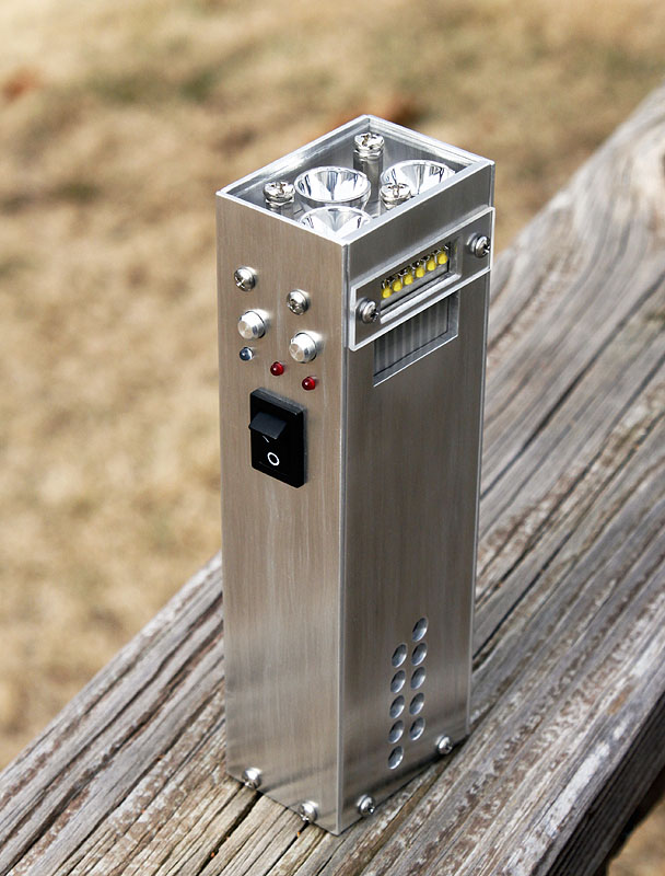
Aside from its functional considerations the unusually high quality of your work has created a device that is very aesthetically pleasing, even beautiful.

Brightnorm
 

CKOD

Enlightened
Joined
Aug 3, 2010
Messages
708
Thanks for the advice Jeff and Mike, I rebuilt the circuit again and grounded the two inputs on the second comparator that isn't being used, as well as putting the .001uF cap across the output and - input of the comparator and the 10uF cap across the + and - of the power. Unfortunately the dimming/brightening problem persists, although much less so when touching the led heat sink than before... the pot still has the same amount of it though.

Below is a drawing I did of how I have the circuit hooked up.. Any thoughts?

It would be better to tie one input to ground and one to something else besides ground, that way it stays in the same state. If you have them both the ground, then as the ground potential changes during switching etc... it can cause the unused comparitor to change states, and add noise to the power line, etc. All it takes is a tiny change for one pin to be above the other.
 

MikeAusC

Enlightened
Joined
Jul 8, 2010
Messages
995
Location
Sydney, Australia
I would add another 10uF from the Comparator + input to ground.

It's standard practice to Earth all unused inputs - provided you have a good ground point.
 

jeffosborne

Enlightened
Joined
May 15, 2007
Messages
252
Location
southern Indiana
Jason 77, your schematic looks fine EXCEPT - (1) I would get rid of the .001 capacitor at the sense resistor, and (2) check the voltage at the positive input of the comparator with the potentiometer set to max. .05 volts gives you 1.0 amp. I get .045 volts there at 850ma, for example. Also, I sent you a private message, not sure you check your forum messages... Jeff
 

Potato42

Newly Enlightened
Joined
Feb 9, 2010
Messages
106
Jeff that is a great looking light you came up with! I'm wondering if you have any long term reports from using the light? How has it held up? Have you modified it any further? Have you made any newer versions? I'm working on a design myself and this light has been a huge help and inspiration. Thank you very much for detailing the build.
 

Illum

Flashaholic
Joined
Apr 29, 2006
Messages
13,053
Location
Central Florida, USA
This is not a flashlight, this is an indoor studio light :)

Jason 77, could it be that your issue lies in the use of a current sense resistor at 5% tolerance and an logarithmic pot as opposed to a linear taper?
 
Last edited:

jeffosborne

Enlightened
Joined
May 15, 2007
Messages
252
Location
southern Indiana
Howdy Illum, Potato42 and rokspyder!
I can report that the high-CRI light has been getting a workout. At Christmas the family group photos were better than ever. Baby Noah comes every 3 months for new pics and I really enjoy that, and I did some product photography recently for my daughter's etsy site. My son used the light for a college graphics design class project, titled the Cinderblock. rokspyder, I hope this will suffice for that ever-popular night time shot:
block_photoscene_01.jpg

Here is the title page from the Cinderblock booklet he produced, also made using the high-CRI light:
block_005.jpg

The high-CRI light remains unmodified. But I have made a new light that helps to fill-in with my photo lighting setup, Hydra-3. It is a non-high CRI neutral white Rebel-ES 1000-lumen flashlight and 2,000 lumen floodlight. It does have a light-stand fitting like the high-CRI light:
Hydra-3_deck_02.jpg

I plan to post a complete write-up for the Hydra-3 soon.

Jeff O.
 

Potato42

Newly Enlightened
Joined
Feb 9, 2010
Messages
106
Thanks for the follow up Jeff! That Hydra-3 looks interesting as well. I see you used reflectors in that one. I am thinking of something along the lines of both your designs combined, although a bit larger. I found a company that extrudes heat sinks in a number of different sizes to use as the base. Where did you get the aluminum and what kind is it? It doesn't appear to be annodized, but perhaps you clear coated it? Since aluminum oxidizes so readily, I'm wondering if you've noticed any changes in the finish of your light. Also if you'll indulge one more question, why did you opt to build your "driver" rather than use an off the shelf component?
 

onetrickpony

Enlightened
Joined
Mar 10, 2011
Messages
262
Beautiful work, looks like an industrial piece of art. How many lumens is that putting out? Someone needs to build something like that with a bunch of reflectors or lenses and make a cannon of a search light with high cri (ha!).
 

jeffosborne

Enlightened
Joined
May 15, 2007
Messages
252
Location
southern Indiana
HarryN, I would be flattered if my ideas are borrowed! Let me know if I can assist in any way. Here's a tidbit of info: my light could have supported 21 or 24 LED's and not just 18. The heatsink and fan operate rather leisurely, and could support more heat removal. More light is often good in the studio.

Potato42, the aluminum is type 30-06, purchased at a local sheet metal shop. The finish on the light has not changed much over time, but I will consider an enamel clear coat for a future light. I built my own driver because I can (electronic design is my occupation), and because I wanted functions that off-the-shelf varieties do not offer. No PWM was one design objective, another being a linear regulator, and not switching regulator.

Jeff
 

fnj

Enlightened
Joined
Dec 2, 2006
Messages
555
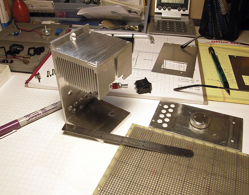
ok I re-did the circuit the best I could to use shorter wires and also to seperate the high power mosfet part from the comparator as well as use a .001uF cap like Mike suggested. I also messed up my previous post as I am using a LM393N dual comparator and not a LM339...

Still having oscillation issues I guess as it still dimms and brightens when I touch or get near the circuit. Also the max amperage the led gets is like 1.3 amps and not the 900mA that I had calculated for this circuit....

Jason 77, if you haven't given up, allow me a silly question. You do realize that you have to supply ground and V+ to the comparator, right? These connections are not shown in the schematics reproduced in this thread.
 

fnj

Enlightened
Joined
Dec 2, 2006
Messages
555
... The pot controls a voltage level given to one input on the comparator: ...
schematic_current%20regulators_sm.jpg

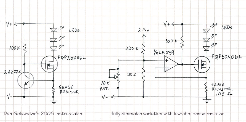
The brightness control is the 10K pot near the center.
Jeff

I'm more than a little confused by the schematic as given.

1) At max pot setting, the + input is connected to a voltage divider of 6.667k / 226.667k, right (the parallel of 10k and 20k being 6.667k). The 2.5 volt reference, coming through this voltage divider is going to be (6667 / 226,667) * 2.5 = 0.0735 volts into the + input - right? The comparator is going to drive the MOSFET so as to make the - input approach the + input. So the voltage across the 0.05 ohm sense resistor is going to be 0.0735 volts - not 0.045 volts. That equates to a current through the sense resistor of 0.0735 / 0.05 = 1.47 amps - right? Not 0.9 amps, or 0.85 amps. So where am I going wrong?

2) What is the purpose of the 20k fixed resistor? Wouldn't the voltage divider be just fine with a single fixed resistor in series with the pot? I am guessing maybe the fixed resistor is to lessen wiper noise on the signal.

3) What is the purpose of the 100k resistor? Is the LM239 an open drain guy?
 
Top