12V G4 15-20W DIY LED remplacement

Mkala

Newly Enlightened
Joined
Sep 3, 2010
Messages
70
Location
Switzerland
Hi all :wave:

After searching and tested some G4 replacement lamps, I decided to try to build my home made solution :)

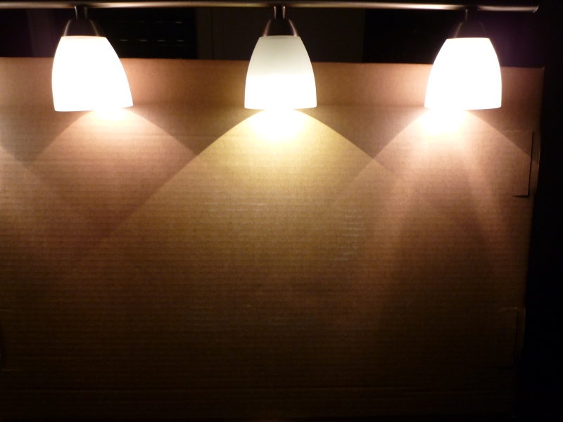
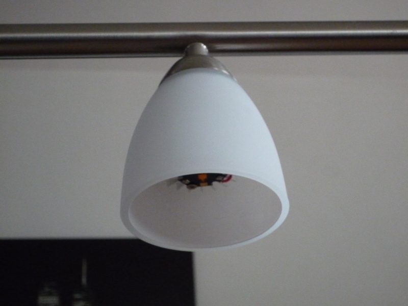
The target light fixture (is it the name ?) is this :

lamp_fixture.jpg


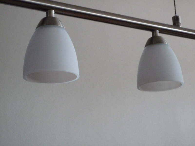
This is a lamp for dinning table, which have 7 lamps at 20W each, total 140W plus losses in electronic PSU it should be about 150W.

20W G4 lamps mean about 220lm, it should be hard to achieve this with LED. The main problem is thermal dissipation in space constrained and virtually closed environment (the top of glass "cups" are closed, meaning heat will stay here...).
The second problem is space for electronic, it have to be really small...

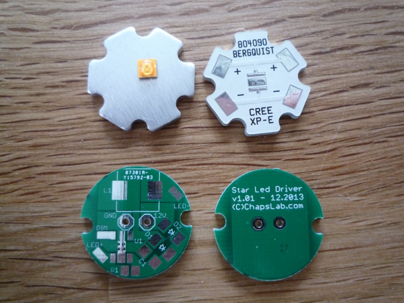
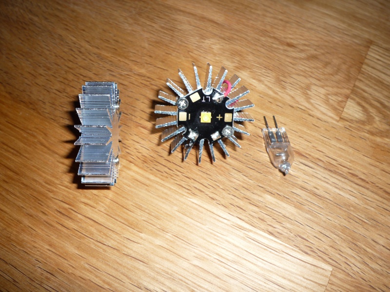
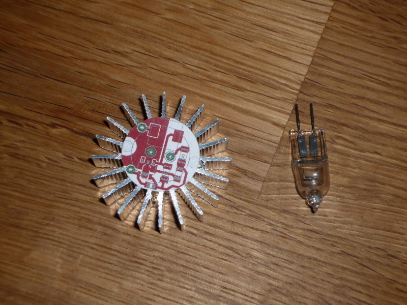
First, ordered some heat sinks, mounted a cree XP-E high CRI (>90). The main drawback is light output, only 80lm at 350mA.
For this application, I target a current of 550mA, witch result at 120lm. Yes it is a bit low, but halogen bulbs radiate at 360°, this result in a lot of losses in this application.
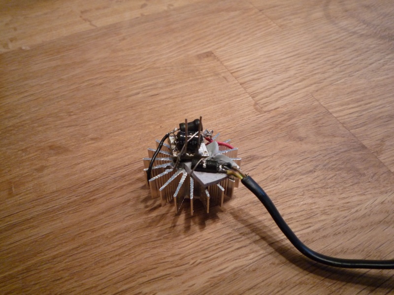
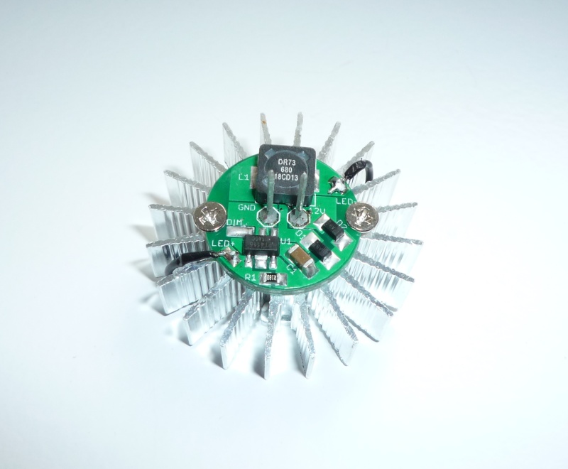
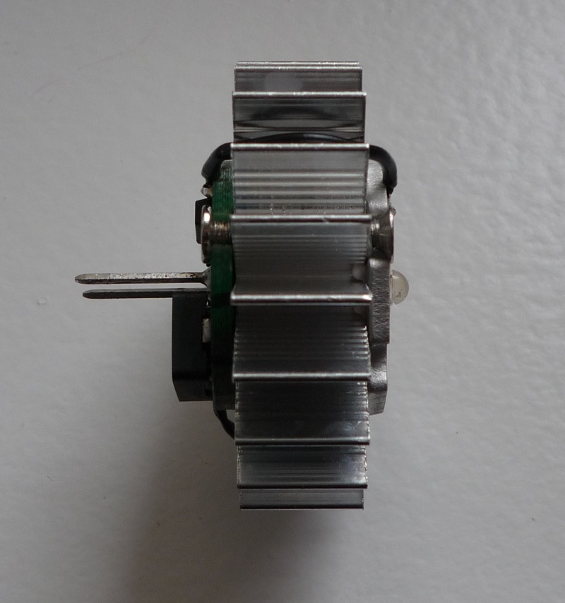
First prototype :

led_proto_1.jpg


led_proto_2.jpg


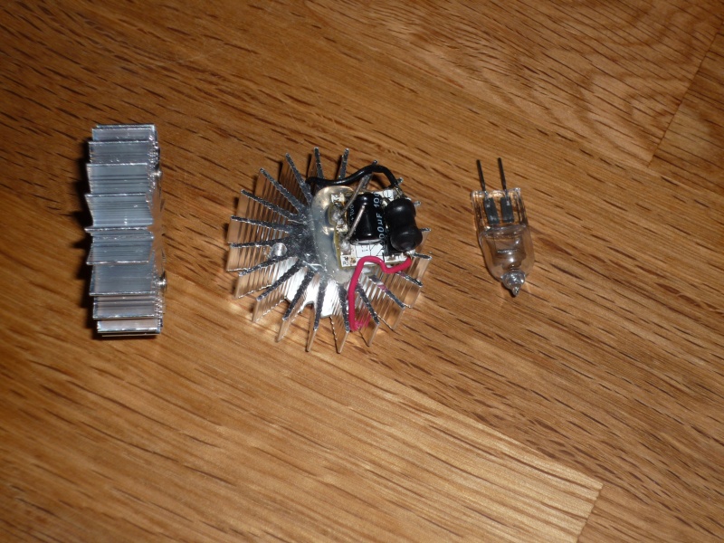
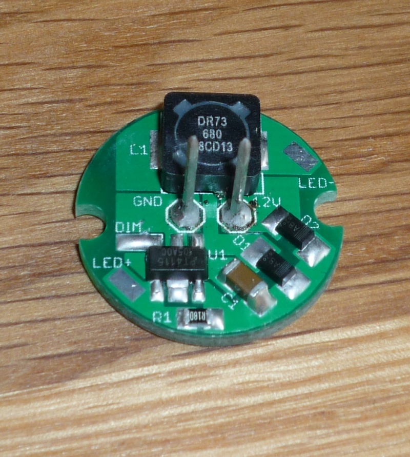
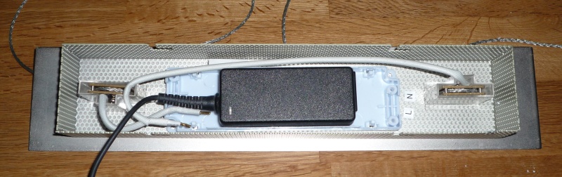
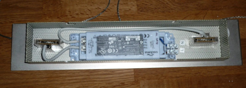
The electronic is from another LED bulb, I have to build a custom circuit :

led_proto_3.jpg


Advices welcome.

Now I should finish electronic design, build 2-3 LED to validate lighting output. If too low, I can increase the current, but I should take care of LED temperature (which is hard to be sure, without IR thermometer)
The other solution is to replace the high CRI LED chip with another warm white chip, more efficient but with bad in color rendering..

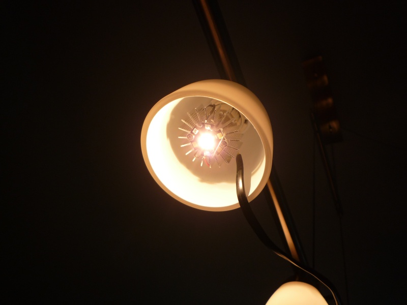
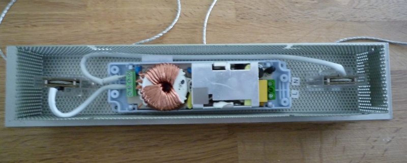
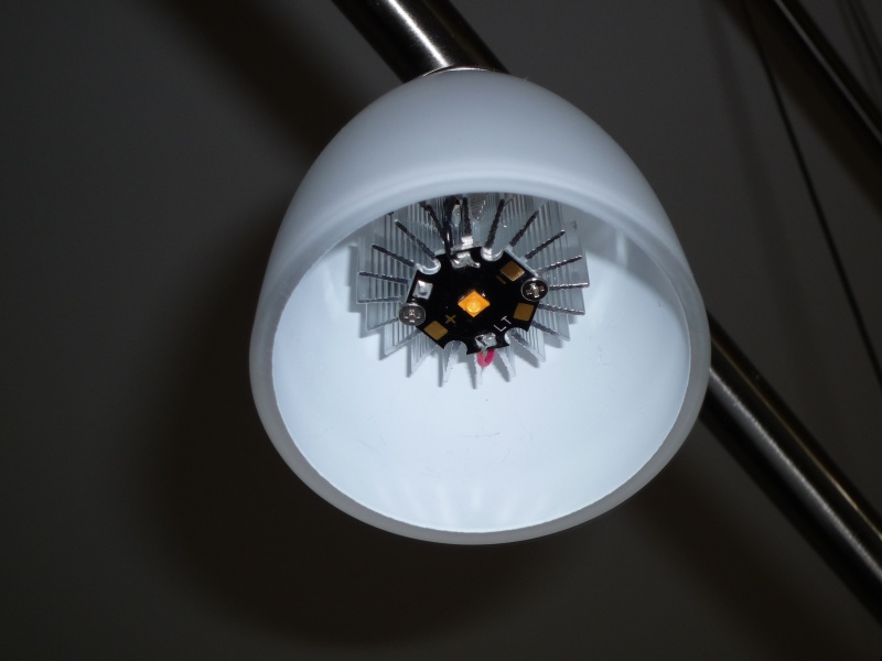
Prototype inside light fixture :

led_inside_1.jpg


led_inside_2.jpg


See u
 
Last edited:

Illum

Flashaholic
Joined
Apr 29, 2006
Messages
13,053
Location
Central Florida, USA
Does your circuit use a driver IC or only discrete components?
With a small heatsink in an enclosed space having little or no air flow, a thermal foldback feature would greatly extend service life. However, a dedicated circuit will add to your parts count. The most cost effective way would be to take advantage of the IC's internal temperature limit, seconded by a op-amp/thermistor circuit.

I have wanted to make the same retrofit as yours, but thus far they all failed due to temperature. Any cover or shroud over the heatsink makes a huge difference :(
 

DaMeatMan

Newly Enlightened
Joined
Sep 25, 2003
Messages
197
Location
Toronto, Ontario, Canada
Looks great so far, however i wouldn't limit myself to just an XP-E. You will get better results with an XM-L. With a U2 bin you should be able to obtain aprox 154 lumens at 350ma, or 239 lumens at 550ma which will give you the same lumen output as the bulbs you are replacing.

I would try a warm white XM-L or two to see if gives you an acceptable lumen output and colour rendering in real world test within the environment where you plan to use it.
 

Steve K

Flashlight Enthusiast
Joined
Jun 10, 2002
Messages
2,786
Location
Peoria, IL
...I have wanted to make the same retrofit as yours, but thus far they all failed due to temperature. Any cover or shroud over the heatsink makes a huge difference :(

I wonder if it would be practical to dump the heat into the metal fixture that the light is mounted to??
 

AnAppleSnail

Flashlight Enthusiast
Joined
Aug 21, 2009
Messages
4,200
Location
South Hill, VA
It's rarely good heatsink fodder. I find that those fixtures tend to be minimal-thin faux-brushed metal with a thick plastic coating on the outside to have the pretty finish on. That said, we're only talking a few dozen watts to dump. I have a 32 inch long aluminum-backed LED strip bar that takes about 24W of electricity and stays at a reasonable temperature.
 

Illum

Flashaholic
Joined
Apr 29, 2006
Messages
13,053
Location
Central Florida, USA
I wonder if it would be practical to dump the heat into the metal fixture that the light is mounted to??

yep, agree with AnAppleSnail on this one, most standard household lighting fixtures are not designed to be heatsinked on. If any, the metal composition would have been designed to inhibit heat conduction as standard incandescent/halogen lamps will run hot, often hotter than the plastic junction boxes some of the modern homes can take.
Only conceivable way to dissipating alot of heat would be a fan, but its noisy, makes mounting very difficult, and its the weakest link in the thermal relief
 

Mkala

Newly Enlightened
Joined
Sep 3, 2010
Messages
70
Location
Switzerland
Thank you for your replies all :)

Does your circuit use a driver IC or only discrete components?
With a small heatsink in an enclosed space having little or no air flow, a thermal foldback feature would greatly extend service life. However, a dedicated circuit will add to your parts count. The most cost effective way would be to take advantage of the IC's internal temperature limit, seconded by a op-amp/thermistor circuit.

I have wanted to make the same retrofit as yours, but thus far they all failed due to temperature. Any cover or shroud over the heatsink makes a huge difference :(
Effectively, the heat will be the hard side to manage. I'll use a PT4115 to drive the LED, it is not really a high end driver, but I think it will do his job. The pros are small size, small external component needs.
It will be hard to add some parts, space is very limited.

Do you have more info of your build ? Lamp size/shape ? power dissipated by the LED ? Pictures ? Thank in advance.

Looks great so far, however i wouldn't limit myself to just an XP-E. You will get better results with an XM-L. With a U2 bin you should be able to obtain aprox 154 lumens at 350ma, or 239 lumens at 550ma which will give you the same lumen output as the bulbs you are replacing.

I would try a warm white XM-L or two to see if gives you an acceptable lumen output and colour rendering in real world test within the environment where you plan to use it.
Thank you for the proposition. Effectively, I can use another LED chip to have better performances or a good compromise between CRI and light output.

But I have not seen a XM-L chip binned U2 in warm white... only cool white.
Tests would be done to determine if I need a high CRI version or if a warm white would be fine. But I will not use a cool white, even not a neutral white. Color temperature should be around 3000-3500k to be fine.


For the dissipation, the metal fixture could handle a bit of heat, but the problem is inside the glass, the socket is in plastic (and it is used to maintain the glass). So it is not easy to transfert heat to metalic part.
 

Mkala

Newly Enlightened
Joined
Sep 3, 2010
Messages
70
Location
Switzerland
I continue my project, slowly...

Temperature is the main concern. I have done some temperature measurement, with a digital sensor attached to the heatsink, thermal pad between.
After 30 minutes, it reach 68°C. The temperature stabilize at 70°C after 1 hour, still same value after two hours. Ambient temperature of the room is 20-21°C.

Some pics :

led_proto_temp_mesure.jpg


led_proto_temp_sensor.jpg


See you
 

Mkala

Newly Enlightened
Joined
Sep 3, 2010
Messages
70
Location
Switzerland
A lot of time later... prject continue :)


PCBs designed and received ! Hop they works.

Electronic components, including Cree LED (90CRI, 80CRI) and thermal MPCB in stock !

pcb_and_mpcb.jpg
 

Microa

Enlightened
Joined
Mar 10, 2011
Messages
256
Location
Hong Kong
I thought you have suspended the project. Good to hear that you are back. Are you still employ the XPE and driven at 550mA?
 

Mkala

Newly Enlightened
Joined
Sep 3, 2010
Messages
70
Location
Switzerland
My projects are always slow I think ;)
I do them when I have time, and I prefer to take time to make things the better I can.

Yes still XPE @ 550mA. With vF at 3.10-3.15, this mean 1.7-1.8W LED power.

I'll test two LEDs :
XPE 90 CRI warm white ~120lm @550mA
XPE 80 CRI warm white ~150lm @550mA

My circuit works good :) Regulation is fine. Mechanical is ok too.

Some pics :


pcb_populated.jpg


assembled_front.jpg


assembled_rear.jpg


assembled_side.jpg


Happy you find some interest in my thread :)
 

Steve K

Flashlight Enthusiast
Joined
Jun 10, 2002
Messages
2,786
Location
Peoria, IL
Nice work! The circuit board turned out quite well.

Is it still leveling out at 70 degrees C? Considering that some LED manufacturers are now rating the LED lifetime at 85C, your light out to last a long time.
(edit: oops.. should have been "your light ought to last a long time")
 
Last edited:

Microa

Enlightened
Joined
Mar 10, 2011
Messages
256
Location
Hong Kong
I concur. The thermal resistance of XPE Qj-c is 9 C/W. The power at 550mA is about 1.7W. The junction temperature is about 85C ( 1.7 x 9 + 70 = 85.3 ). Replacing the XPE by XBD or XPE-2 may be more beneficial.
 

Mkala

Newly Enlightened
Joined
Sep 3, 2010
Messages
70
Location
Switzerland
Thanks !

I have not done any other measure. Since the firsts, current, heatsink and fixture is the same, so temp should be the same. And to be really precise, I should buy an IR thermometer, because its hard to do measures on small pieces, with good contact and no influance.

You think 85° at tj its to high ? I also prefer lower temperatures, but in retrofit we not always have the choice... And LEDs a garanted at 85°, so they should last a lot (and perhaps in five years I'll put new chips because they will be 2 times better)

For the LEDs choice, if you can help me, thanks in advance. The XPE was choosed more 1 year ago, so now new products can be better.
But as always, there are criteria :

- 90 or 85 CRI prefered, 80 minimum
- XPE / XRE / MX6 / XPG footprint, as mouser.com has only these format for Star MPCB (produced by Bergquist)
- higher lumen possible, at 550mA it's about 150% of rated lumens @350mA
- price equal (for less 10 LEDs its not an argument), but orderable in small quantities @Mouser

I already have XB-D Cree chips, but no MPCB to tests them... :(
 

Microa

Enlightened
Joined
Mar 10, 2011
Messages
256
Location
Hong Kong
For home lighting, Tj at 85C is no problem at all. New generation LEDs' lumen output are binned at a more realistic 85C environment. The XPE and XPG are binned at 25C so in fact you will not have 150 lumens output as you have expected.
 

Illum

Flashaholic
Joined
Apr 29, 2006
Messages
13,053
Location
Central Florida, USA
For home lighting, Tj at 85C is no problem at all. New generation LEDs' lumen output are binned at a more realistic 85C environment. The XPE and XPG are binned at 25C so in fact you will not have 150 lumens output as you have expected.


Err... there's thermal resistance on every material. Depending on the assembly and how good/poor thermal relief is concerned heatsink temp is almost always lower than Tj [junction is the heats point of origin] Many manufacturers rate their lamps to run on 85C, but the junction is usually a few degrees higher. 85C is already bordering on the edge of failure within LED specs, imagine what the LED feels like sitting inside an enclosed heatsink inside a fixture. If your homebrew can level at 70C, your units might last beyond any other fixture in your house.

I have a kitchen fixture running eight CREE XR-Es at 350mA 24/7 since 2009, they have dimmed just a bit after 44000 hours of operation. The star temperature measures 30C per LED. I dare say it might last the house at that temperature.
 

Microa

Enlightened
Joined
Mar 10, 2011
Messages
256
Location
Hong Kong
If possible, we should keep the junction temperature lower. However, the junction temperature is running at 85C should be acceptable. I would like to quote Average Lumen Maintenance Characteristics at page 3 of the LUXEON Rebel General Purpose Datasheet DS64
" Philips Lumileds projects that cool-white, neutral-white and warm-white LUXEON Rebel products will deliver, on average, 70% lumen maintenance (B50, L70) at 50,000 hours of operation at a forward current of 700 mA. This projection is based on constant current operation with junction temperature maintained at or below 135°C."
I think if the Ta can keep not higher than 70C which may not be a problem.
 

Mkala

Newly Enlightened
Joined
Sep 3, 2010
Messages
70
Location
Switzerland
Ha yes I forget output was rated at 25°... as you say, not very realistic.
I will buy the new XP-E2, I'am still not decided between 85 CRI and 90 CRI.

For the life of LEDs, I think this is really not a problem. My design is a bit borderline because I always take huge safety margin, but in this case I havent a lot of margin. With actual technology, I need to push the current to the limits to optain the output I need.
In 3 or 5 years, I'am quite sur I could find a great 150lm/W 90CRI LED chip and reduce the current to 350mA. And they will last forever (and longer than me :) )
For the moment, I have not the choice. And it's better to use 15-20W of power with reduced LED life than 150W with halogen.

Yesterday evening, I've done a little test :
light_output_ledcenter_20wbulbsides.jpg


20w halogen - 80CRI ~135LM - 20w halogen

This afternoon, I changed the original "*******" AC/AC electronic transformer. It's not compatible with my DC design. And I need a lot less power...
I integrated a 12V 36W desktop adapter, because it's hard to find industrial SMPS with max 45mm wide and 32mm height with power >20w.
Don't worry for safety, the fixture is earthed (was double insulation, but as the wire of my house are not double insulation... I earthed it when I fixed)
power_supply_change_1.jpg


power_supply_change_2.jpg


power_supply_change_3.jpg
 

Illum

Flashaholic
Joined
Apr 29, 2006
Messages
13,053
Location
Central Florida, USA
well, if the SMPS's IEC connector is polarized, make sure you use a meter tool to determine which ones line and which ones neutral. Fuse the line side with a fuse that is rated [give or take] twice the maximum input current. Remember now, enclosed SMPS's meant for portable electronics aren't always designed for 24/7 usage. More than likely you can get away with it even in an enclosed space, but a fuse adds a piece of mind.

The projects really coming along, :kewlpics:
 

Microa

Enlightened
Joined
Mar 10, 2011
Messages
256
Location
Hong Kong
They look very nice. The LED seems brighter projection on the wall than the halogen. If you are not very concerning about the cost, XPG-2 85CRI and 90CRI can provide Q2-Q3 for 130-140 lumens at 550mA ( Tj = 85C ). Did you try this design tools?
http://pct.cree.com/dt/index.html
 
Top