Busch & Muller S6 Dynamo Failure

heckboy

Enlightened
Joined
Sep 23, 2007
Messages
247
Hello all.

I've been running a BM S6 dynamo on my commuter bike. I've had a number of lighting setups hooked to the dynamo, must recently a Supernova E3 headlight and taillight. I was bombing down a local hill, when my lights went out! When I went back and looked at my cyclometer I was probably going 45 MPH when the lights went out.

I pulled the dynamo off the bike and spun it with a drill motor. I wouldn't light a known good light. I then checked the resistance and got .2 Kohm and found a max voltage of .2 VAC. Mechanically, the dynamo feels just fine. I'm curious, what is the likely failure mode here? I am considering that the failure might be with the current limiting circuitry in the dynamo.

What do you think? I'd like to repair this dynamo if possible and I'm hoping someone has some experience with this before I start taking it apart.

Thanks,
HB
 
Depending on which S6 you had, you might simply have shredded it. The original S6 was rated for a top speed of 50 kph (not sure how many mph that would be) when loaded with a 6V/3W lighting system. Change the load or go faster and you run outside the specification.

The later S6 did not have the 50 kph limit. Still, I don't know what your setup would draw - increased current and/or reduced load both may contribute to overload the dynamo's electronics.

In both cases, the likely failure is the electronics inside the dynamo, which means that you'll have to open it first. Maybe Olaf Schultz has some stuff on his site (www.enhydralutris.de - all in German).

Bye
Markus
 
50 KPH is about 31 MPH which I've exceeded about every day (I live in a hilly region). I can't find anything that refers to a speed limitation for the Dynmotec S6. It wouldn't surprise me if there were a maximum operating speed for the dynamo, however, I'd expect to find it readily.

I ran Olaf Schultz's website through Babelfish and didn't see anything that looked helpful, but thanks for the reference. It is an interesting site.

What I'm now considering is that if the dynamo itself is still operational and it's the current limiting circuitry that has failed I'll build a replacement circuit outside the dynamo if needed.

Regards,
HB
 
Can you isolate the failure to the dynamo? i.e. were the measurements for resistance and voltage made with the lights disconnected? Just wondering if the headlight might have been damaged instead.

I seem to recall something about the S6 having a voltage limiter, and if the headlight doesn't draw the full 0.5A, I can imagine that you could have over-volted the limiter circuitry. If you can get inside the dynamo, you might be able to remove some of the limiter circuitry, but there are obviously risks associated with this. Of course, if the dynamo can't be fixed otherwise, then you don't have much to lose.

In the past, I built a series voltage regulator for the purpose of charging a battery with a Schmidt hub dynamo. It was an educational experience, and I learned that a Schmidt can produce over 100v when coming down the hill at 50mph. As a result, I had to use parts rated for 100v, even though it was nominally a 6v regulator. 100v parts are big and expensive, so I can understand it if B&M didn't use them.

my sympathies,

Steve K.
 
My first thought was that I'd fried the lights. I don't have a bunch of run time on the Supernova system so I've not built up a lot of confidence in that system yet. I did note though that after I'd pulled off the road that the stand lights were still operating in the Supernovas. When I got home I connected a known good light to the dynamo, a Inoled, and it failed to light.

I did perform the voltage and current checks with no lights on the dynamo.

Regards,
HB
 
I did perform the voltage and current checks with no lights on the dynamo.
then the ac voltage should go up (till a bit more than walking speed) and then stay fixed at something like 7.5 V

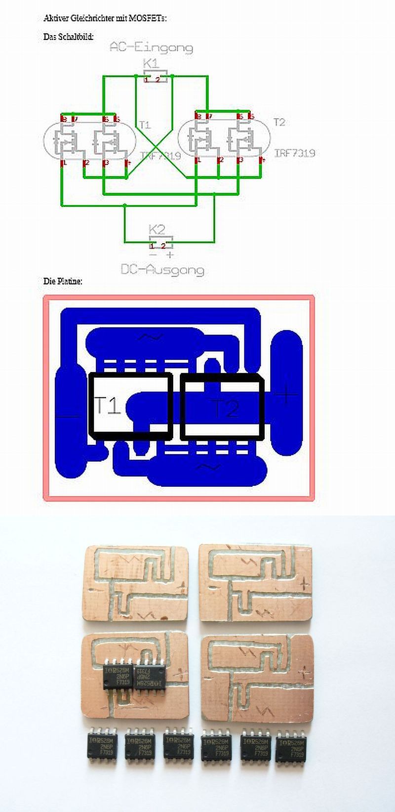
If You can not get it to work again, be4 throwing it away, try to remove the whole electricity inside.
Doing so You have to add Your own rectifier device and take care for the light, as the dyno now has no problem delivering Voltages of 20-30 V (when it does not slip).


I am posting the usual MOSFET-device once again ;)
the best and most efficient (and smallest) device I know so far.
(PS: use a suitable amount of led! I have another dynamo in such a setup and it delivers 940 mA to three series connected led at 25 km/h)

b3zyv0pw5wqse5eoa.jpg
 
Nice. How large is the board you've got pictured? I'm planning to take the dynamo apart this Saturday. I'll let you know what I find.

Regards,
HB
 
the black mosfets are 5*4 mm,
when You see them for the 1st time, they are really small ;)


(but I cut the boards with a dremel, its all possible)
 
I don't know these dynamos but I'd be surprised to learn they contain electronic circuits. Dynamos are inherently self-current-limiting in their magnetic induction working principle. Unloaded however at high speeds they can produce voltages high enough to break through insulation or damage electronics. Therefore voltage regulators for dynamos are usually of the shunt type, not the common series regulators.
The resistance reading you got, was it any different from shorting the test leads?
0.2 kOhms = 200 Ohms. I believe 0.2 Ohms is the correct observation, which would indicate a short-circuit in the dynamo.
 
the higher priced (like the Dynotech) dynos seem to have some kind of driver inside to
a) ramp up voltage at low speed
b) protect at higher speed (which obviously not work every time) ;)

the cheaper ones feature antiparallel 7.5 V Z-diodes


this is what was inside my Lightspin:
b5nzfjbzika32so7e.jpg

not too easy, eh?
 
Jeeezz...
Things have happened since the last time I opened up a dynamo..
No wonder they can fail, & not too easy to fix, laquered smd's & all.. In my experience zeners are prone to short out if abused ever so little..
 
Top