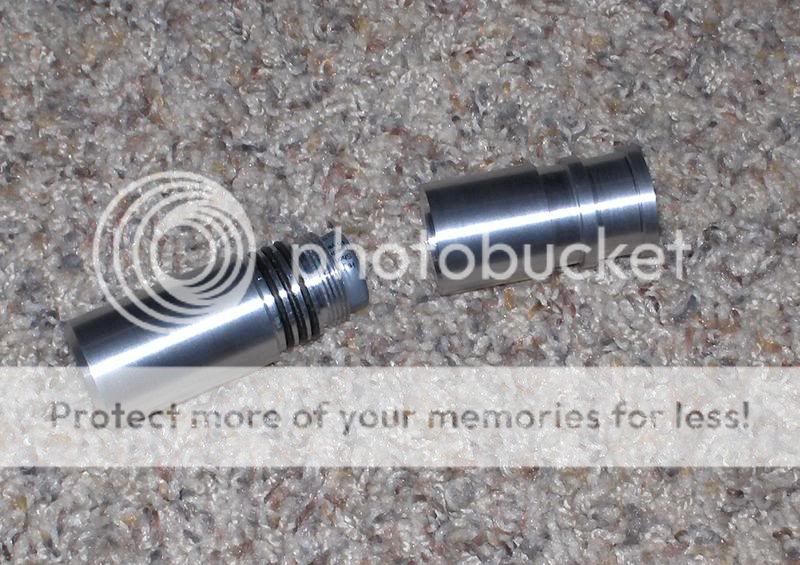
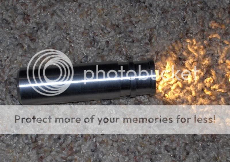
CR123A Flashlight model.

VanIsleDSM

Enlightened
Joined
Oct 16, 2007
Messages
649
Location
Victoria BC, Canada.
I just downloaded google sketchup yesterday. At first it was odd to get used to, but I seem to be getting the hang of it now. I knew I needed to start doing 3D models to make the machining work easier, rather than just figuring it out as I go along. I learned a lot doing this, now I'm eager to make some more models, but I think I'm gonna go have a whirl at machining the head of this thing right now. I'm not entirely sure how long to make the body yet, depends on which driver I decide to use. I ordered 3 different single cell drivers to test them all out and decide which I want to use. The different heights of these drivers will decide how long the body has to be.. that and the fact that DX didn't list all the specs for the clicky switches I ordered.

I've got a CREE R2 WH I'll probably put in here. Also picked up a couple of those 19mm AR coated glass lenses from KD, but I'll have to shave them down to ~18mm to work.

Planning to silicone the lens in at the front, and silicone the tailcap rubber protector in as well. Then there's the 3 O-ring seal designed to work with 21mm OD 18mm ID O-rings. I used this chart to help me design the specs for the O-ring seals: http://www.norseal.com.au/tolerances/ormach.htm (Thanks Dom)

Hopefully that'll be enough that I can submerge the light without any problems. Not for diving, but just some snorkeling maybe. Once it's built I'll take it down to 20ft or so with no battery to see if it comes up dry.

As for the threads, they don't really go anywhere. I don't know how to make them helical yet, I think you need to write script and such. I'm happy with the straight around threads, they do well enough for measurement. They're 24TPI.
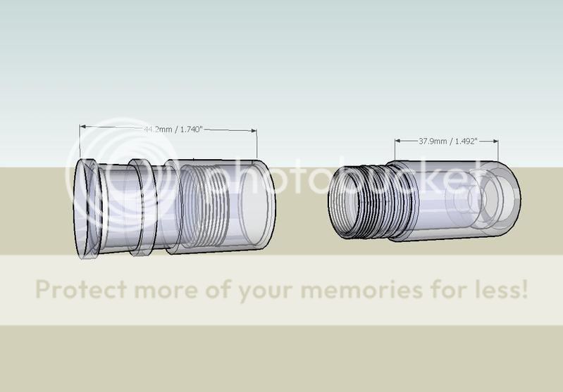
16340Front.jpg


16340Back.jpg


Body.jpg


Head.jpg
 
Last edited:
did you have any expiriance with cad programs before?
thats pretty good for one night with the program.
 
To get the flat spots on the bezel's edges as shown in the drawing, just loosen the gibs in your compound. It will chatter like the ****ens but you will see some interesting flat spots when you turn it. :)


Seriously, that's a nice piece of work and I look forward to the physical incarnation.

Daniel
 
Thanks for the compliments. No CAD experience before this. Pretty nifty program. The hardest part was figuring out how to make things accurate, getting the program to do what I wanted.. like finding the center of a circle to start another line or something.. Once I got the hang of that kind of thing it was pretty easy. Moving around in 3D to access what you want, or to get a good angle to work from also takes some getting used to.

As for the materialization.. I made the head tonight! Took about 4.5 leisurely hours from a solid 1" bar. Came out very nice, I'm really happy with it. I made slightly booboo on it, on the easiest part! The fins on the outside. When I made the first cut on the outside I just went in the width of the parting blade and then moved 6mm away and started another cut.. like I used to make all my heatsink fins.. (before I used thermal modeling software, footnote about this) So I ended up having to extend the first fin gap to 9mm, and the second fin gap is 6mm as shown.

About the thermal modeling software.. I realized that an airspace the width of the parting blade does virtually nothing. Depends on fin height, but even fins only 1.5mm high still want about 6mm in between them to work properly. Larger fins should have around 10mm in between them for natural convection cooling. Anything less really hurts the cooling performance.. those ~1.5mm cuts taken with a parting blade really barely do any better than a solid bar.

Don't have my camera on hand right now. I'll take some pics tomorrow and post them up.

Now I can't wait to get the different drivers I ordered from DX and KD, along with the silicon tail cap for the switch, the switch itself, and the o-rings. Then I can finalize the length and make the body.
 
To get the flat spots on the bezel's edges as shown in the drawing, just loosen the gibs in your compound. It will chatter like the ****ens but you will see some interesting flat spots when you turn it. :)


Seriously, that's a nice piece of work and I look forward to the physical incarnation.

Daniel
:crackup::crackup::crackup:
 
To get the flat spots on the bezel's edges as shown in the drawing, just loosen the gibs in your compound. It will chatter like the ****ens but you will see some interesting flat spots when you turn it. :)

Daniel


Heh.. Something similar happens when you forget to lock the piston on your QCTP.


Ok, I got the pics. Something else I changed slightly from the model is that the first groove in the head starts at 1mm and slopes down to 1.5mm. I did this because I want to make a groove inside the head, right behind the lip where the lens will sit. So the lens will be pretty tight all the way down the bore, but once it reaches it's sitting area it will be able to move around in it's groove.. and I will fill this groove with silicone.

P1010680.jpg


P1010682.jpg


And a couple with the reflector I'll be using in there, along with a piece of plastic I cut out of a flat sheet.

P1010683.jpg


P1010684.jpg


Now I can't wait to machine the body.. but I have to wait until I have everything and know the dimensions of it all.. oh well.. back to making more 3D models for now.
 
Last edited:
Updated 3D model to reflect the actual piece:

I haven't actually cut that grove for the lens yet.. I did cut it, so I knew when to stop boring from the other side so I didn't take out the lip to hold the lens in, but I didn't go deep enough, I'll have to re-chuck it and do that over. Just poke in another 0.5mm.

16340final.jpg
 
Last edited:
That's pretty cool. Think if I sent you a DXF file you could use sketch-up to turn it 3D for me? I can't seem to get it working ,since I run Linux. :D

Oh, a nice free tool for 2D-CAD is QCAD. I've found it to be better than Auto-CAD for what I do. :D
 
You should make sure that you reflect all your ad-hock changes on your drawings before you cut them.

"Why?" you may wonder? It's to avoid conflicts in design decisions as well as documenting what you do so that you can recreate the piece if you accidentally over bore or cut it too short.

An example; I made a beautiful little light. I made it as thin as possible. A real work of art. Then I read a thread that advocated o-rings to keep threaded parts from getting loose. So I re chucked it and cut a very accurate .023 deep groove just behind the threads.

Un-fortunately the wall was only .020 thick. I'd made the inside bore larger than my plans in order to fit the converter, and never changed the drawings.

It's heartbreaking to watch your light split in two.

Daniel
 
this is the cad i curently dont know how to use lol
http://www.alibre.com/xpress/

its free and you can put parts together to see how thay fit.

Wish I could use that, but if I'm gonna spend the time to set it up in Wine, I'd just as soon use the copy of autoCAD I've got laying around. :D
Can't wait til Blender-CAD is finished. :naughty:
 
Last edited:
Still waiting on parts from DX and Kai.. DX ones are on the way now at least.. but I never got any contact from Kai about what was going on at all.. only a paypal receipt, but I heard that's normal operation for them.. hopefully the parts from Kai arrive soon too. I sure prefer the informative nature of DX.

I have 3 different 1 cell drivers coming to test. 1 from DX and 2 from KD, see which one ends up working best..

I couldn't wait to start machining the body, so I did.. even though I knew I'd have to take it out of the chuck before I could finish it, but I'm ok with that, I'll play with it enough to get it nicely centered again.. threading and OD work is all done anyway.

I'm going for the seamless look. Few scuffs on it now, since it's been sitting around unanodized for a couple weeks.. just had to keep the thread alive with some new pics while I wait.

P1010688.jpg


P1010691.jpg


Eager to finish this, hurry up parts!
 
Got some stuff from DX and KD today, tested 3 different single cell LED drivers and they all suck. I put in the 3x7135 dual mode board, low and high. It's the best I have right now, I'll be making myself a proper single cell buck-boost driver soon.

Put in a warm white CREE, N2 flux 8B tint, 2720K-3050K. Very nice colour to it. I still have to take it back apart though to anodize it. This aluminum is pretty soft, it's 6061, but I don't think it's heat treated, pretty gummy stuff I just had laying around. I'm going to go buy some 7075 tomorrow and make another one that I'll put a WH tint R2 CREE into.

Here's a couple pics, I tried to take a beamshot but I only have my old junk camera right now, and program the shutter, so it was way overexposed and looked like crap. I'll get a proper beamshot tomorrow.

HPIM1418.jpg


HPIM1419.jpg
 
Very nice Van
Great work on you first light AND CAD as well!
I can see the color of that LED would be very soothing on the eyes.

The Cree WH is a very nice tint as well.

I'll be VERY interested in your buck/boost driver -as i'm sure many people will.

You'll probably start another thread on it but if not ,mind if i ask a few questions? :)

Will it be 17mm dia. like the ones you tried?
Will it have different current levels?
Can you make it so it uses a momentary switch?

I don't think there is a driver like that out there that can be got easily -if at all.

Cheers
Dom
 
Nice looking light! Must be pretty hefty in the hand. One thought - your detail drawing of the threads (third from top) looks overconstrained.
 
Thanks guys.

About the driver, the only one I've seen similar is the GD1000, looks like a nice buck-boost, but no current control. I've been looking around for a good chip to use, and I found one that I could do 2 brightness levels with a switch like this: http://www.dealextreme.com/details.dx/sku.5604. Or up to 3 brightness levels with a switch that connected 1, 2, 1+2, or with a potentiometer. I'll look around a little more to see what's out there, but I'm always up for suggestions. I'd be making it 17mm, but using a momentary switch would add some difficulty.. unless you're programming you're own PIC to run the board, it's much easier to go with a clicky.. no parasitic draw that way either... not that it's much.

The threads, they just look that way I suppose because of the angle. They're the same size as the real threads, they're just not helical in the drawing. As for being hefty, I guess I should take a photo of it in my hand, it's quite small.
 
I received the sample chips for the driver, wow they're small! 3mmx3mm 10 pin DFN package. Soldering iron is out for this one.. Rigging up an SMT hotplate right now, been meaning to for a while, and now I have a good reason.. I've always etched my own boards, so I'll try to etch my own prototype for this as well, but I may fail, it's so small. For any type of production, a soldermask on some production boards would be a must.

The driver incudes many nice features.

Overtemp shutdown

Undervoltage shutdown. If you're using an unprotected Li-Ion it won't drain completely dry if left on, a full shutdown will occur at 1.9V

Soft start

Vout runaway clamp. This is important, no load protection is basically what it is. Many boost or buck-boost drivers are destroyed if no load is connected because Vout just keeps going up until the chip/output capacitor are destroyed.

Forward current limit. Protection against a shorted LED.

Reverse current limit. Protection against a reverse connected battery.


I'm adding a small micro controller to the board as well to switch between 3 outputs, 350mA, 650mA, and 1000mA. I could any program any type of custom flashing or strobing routine aswell.

I'm considering the momentary push button aproach, as this chip consumes nothing when shut down, but the micro will consume a bit, but I think I can get it down low enough not to matter. But then what is the point? I'm already using a clicky with a spring already attached, just drops right in, if I went full momentary I would have to change the switch. I suppose I could make it a little smaller with a momentary, and the switch would last longer, but what other benefits are there to the momentary switch Dom? I could always make 2 versions I suppose, it would only be a software change.

Playing with programming the micro right now, but I only have a DIP package.. I'll need to order some SOIC packages for the driver.
 
Top