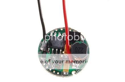
DX Driver Board Tests - Efficiency Results Included

eprom

Newly Enlightened
Joined
Apr 17, 2007
Messages
146
Location
Turkiye
Update :

10/06/2010 - DX 1.5V~4.2V 3W Step-Up (Boost) Driver SKU.25505, Test results at post #79
02/08/2010 - DX 5V~8.4V 15W 5*Cree Step-Up Driver SKU.26106 Test [Detailed] at post #46
11/20/2009 - I have drawn back the PT4115 chip results for checking them again.
11/17/2009
- Test Results for 2*, 3*, 4* serial connected XR-E driven with Mr16 1*3W Driver. results on #28
11/16/2009 - Added efficiency table for Mr16 1*3W Driver (PT4115 Chip) at post #23

Hi Friends,

I have ordered these DX sku.3256 boards about 40 days ago at last I have received them. Theese were totally revised versions, no more using Zetex C310, uses new chip with lots of advantages. I make some measurments. I have measured standart configuration. Add a 1 Ohm paralel resistor to R27 sense resistor and make some more measurments.

At standart config board gives a solid 0,91A from 4V to 16V
At hacked config board gives a solid 1.16A from 4V to 16V

+No heat (Also hacked 1.16A config)
+Very solid I out
-Sense resistor eats the efficiency (but also has 90% efficiency)

And measurment table,

Efficiency_Corrected.jpg


Note: I wrote "Efficiency of Board without Sense resistor" this is a wrong expression I think. If we have a chance to use board without Sense resistor (But we can not) and all the power (Pout and Psense) goes to a LED, what would be the board efficiency.

Thanks,
EpRoM
 
Last edited:
Re: Newly Designed DX Buck Driver (Kennan Like) 90% Efficiency

Hi Friends,

I have ordered these DX sku.3256 boards about 40 days ago at last I have received them. Theese were totally revised versions, no more using Zetex C310, uses new chip with lots of advantages.

Don't leave us in suspense, what chip does it use now? By the way, the last time I ordered these I think they actually had a C300, but nearly the same.
 
Re: Newly Designed DX Buck Driver (Kennan Like) 90% Efficiency

It is hard to say because chip top was sanded.

But my suggestion is AX2002, because I used PT4105 at 1 amp level and efficiency was only 70%. AX2002 datasheet specs are very close to my findings.

Datasheet of AX2002 = http://www.micro-bridge.com/data/Axelite/AX2002.pdf

Edit:

I have controlled the Pt4105 and PT4115 datasheets. Neither of them can drive led at ~1A with R27 resistor. Only AX2002 can do this.

PT4105 can drive led ~700ma with R27
PT4115 can drive led ~350ma with R27

Don't leave us in suspense, what chip does it use now? By the way, the last time I ordered these I think they actually had a C300, but nearly the same.
 
Last edited:
Re: Newly Designed DX Buck Driver (Kennan Like) 90% Efficiency

I think you have a small math error. Your calculation of Pout is the power draw of the LED, based on Vf*If. That number should not change regardless of what the sense resistor loss is. The LED is still going to draw the same power.

To estimate what the efficiency could be for an ideal sense resistor setup that draws no power, you should subtract Psense from Pin to get the amount of power that the driver would have to deliver without being weighed down by any sense resistor losses.

It is interesting that your measured drive currents of 0.91A and 1.16A are almost exactly what you'd calculate based on the sense resistor formula in the AX2002 datasheet.

Check out KD1640. That driver also uses the AX2002 buck IC.
 
Re: Newly Designed DX Buck Driver (Kennan Like) 90% Efficiency

Hi Justin,

System efficiency calculated by Pout/Pin
Ideal System calculated like all the Power (Pout and Psense) goes to an virtual LED. This Pout and Psense feed by Pin at last. Yes you are right but I can not get the measurments/numbers of system without sense resistor so this is the only way I can do.

Thanks for your comments,
EpRoM

I think you have a small math error. Your calculation of Pout is the power draw of the LED, based on Vf*If. That number should not change regardless of what the sense resistor loss is. The LED is still going to draw the same power.

To estimate what the efficiency could be for an ideal sense resistor setup that draws no power, you should subtract Psense from Pin to get the amount of power that the driver would have to deliver without being weighed down by any sense resistor losses.

It is interesting that your measured drive currents of 0.91A and 1.16A are almost exactly what you'd calculate based on the sense resistor formula in the AX2002 datasheet.

Check out KD1640. That driver also uses the AX2002 buck IC.
 
Last edited:
Re: Newly Designed DX Buck Driver (Kennan Like) 90% Efficiency

Yes, I know that efficiency is Pout/Pin. What I am saying is that when you calculate your efficiency without the power drain from the sense resistor, your efficiency equation should be Pout/(Pin-Psense), not (Pout+Psense)/Pin.

Pout is a constant. If you have a constant current driver and it sends If to the LED (resulting in a voltage Vf), then Pout will be If*Vf. It doesn't matter if you have a sense resistor power loss or not. Adding Psense to Pout doesn't make any physical sense.

With a sense resistor power loss, the driver has to generate that much more power so that it can deliver Pout to the LED. That means Pin includes the sense resistor power, which reduces the efficiency percentage. By subtracting Psense, you estimate the higher efficiency you'd get if the driver didn't have to generate the extra wattage to feed the sense resistor.
 
Re: Newly Designed DX Buck Driver (Kennan Like) 90% Efficiency

I looked like this,

Isense resistor connected serially to the LED so IC work like pushing a LED with 3,61V Vf + 0,25V Isense resistor. I mean system work like pushing a LED with 3,86V Vf at 1.16A. So I used this equation to calculate and this is my point of view.
 
Last edited:
Re: Newly Designed DX Buck Driver (Kennan Like) 90% Efficiency

So with that in mind, has anyone done the actual numbers?
 
Re: Newly Designed DX Buck Driver (Kennan Like) 90% Efficiency

Nice work. Could you measure 4 V and 4.5 V input please.

I have controlled the Pt4105 and PT4115 datasheets. Neither of them can drive led at ~1A with R27 resistor. Only AX2002 can do this.

PT4105 can drive led ~700ma with R27
PT4115 can drive led ~350ma with R27
The PT4115 needs over 8 V anyway.
 
Re: Newly Designed DX Buck Driver (Kennan Like) 90% Efficiency

I looked like this,

Isense resistor connected serially to the LED so IC work like pushing a LED with 3,61V Vf + 0,25V Isense resistor. I mean system work like pushing a LED with 3,86V Vf at 1.16A. So I used this equation to calculate and this is my point of view.

But what is the source of the feedback pin voltage? Isn't it from the reference voltage built into the IC, with an error amplifier providing the feedback? Hence, this power drain seems to be an inherent part of the driver, not the load. It also seems more traditional, at least IMO, to consider driver efficiency as the ratio of the power drawn by the device/load of interest (the LED) to the power drawn by the driver. It would seem less sensible to include other sources of power draw in the numerator. Also, if you are considering a hypothetical driver that doesn't burn any wattage in the sense resistor network, then shouldn't you be subtracting off that wattage, not adding it in, when making that efficiency calculation?

Either way, the difference in the calculated efficiency is small. Just trying to use the right formula.

BTW, do you have a photo of the driver?
 
Last edited:
Re: Newly Designed DX Buck Driver (Kennan Like) 90% Efficiency

Hi TorchBoy,

The board starts to regulation at ~0,5V over the Vf.

At 4,08V board start to hold regulation for my sample.

EpRoM

Nice work. Could you measure 4 V and 4.5 V input please.


The PT4115 needs over 8 V anyway.
 
Last edited:
Re: Newly Designed DX Buck Driver (Kennan Like) 90% Efficiency

The board starts to regulation at ~0,5V over the Vf.

At 4,08V board start to hold regulation for my sample.
Ooh, that's nice. Thanks for checking that. I wonder how low it'll go. Do you have any LEDs with a lower Vf? And will it happily drive more LEDs at once?
 
Last edited:
Re: Newly Designed DX Buck Driver (Kennan Like) 90% Efficiency

I am using it with Cree MC-E parallel wired, Vf= 3,10V @1.16A on 4D maglite. Input is 5.3V 0,77A with Energizer D size Alkalines.

EpRoM

Ooh, that's nice. Thanks for checking that. I wonder how low it'll go. Do you have any LEDs with a lower Vf? And will it happily drive more LEDs at once?
 
Re: Newly Designed DX Buck Driver (Kennan Like) 90% Efficiency

Sounds ideal. When will that setup drop out of regulation? Will 16 V input drive the four dice in series?
 
Re: Newly Designed DX Buck Driver (Kennan Like) 90% Efficiency

Do you have any LEDs with a lower Vf?

I have a KD1640 (another AX2002-based buck driver) order in-transit and plan to test it on an XP-G R4. On another XP-G R4 driven by 3xAMC7135, I measured Vf ~3.1V (tx101 also measured 3.1V when using an SOB1000). With an SOB1227 (1196mA measured drive current), I got Vf ~3.3V.

I have another AX2002-based KD1640 driver that's mod'ed to deliver 1400mA, and it runs a 2S2P MC-E in regulation at ~7.0V in (Vf ~6.2V). In comparison, an SOB1227/2S2P MC-E reaches regulation at ~8.1V (Vf ~6.3V) and an SOB1000/2S2P MC-E reaches regulation at ~7.6V (Vf also ~6.2V). The SOB1227/MC-E case seems anomalous -- not sure why the voltage overhead is so high. The SOB1000/MC-E overhead seems in-line with what I'd expect.
 
Re: Newly Designed DX Buck Driver (Kennan Like) 90% Efficiency

Is the overhead related at all to the drive current or the number of LEDs driven? Or is the overhead fixed? I wish I had a better test bed.
 
Re: Newly Designed DX Buck Driver (Kennan Like) 90% Efficiency

The overhead probably is weakly/moderately dependent on drive current, to the extent the "parasitic" voltage of relevant components depends on current. For the SOB, I think that the two biggest drivers are 1) the buck IC duty cycle is not 100% (it's 87% max), and 2) the Schottky diode forward voltage spec is relatively high at 0.5V. For example, for voltage overhead component #1, the dependence of the voltage overhead on drive current is through the resultant LED Vf. The voltage overhead = Vf/0.87 - Vf ~ 0.15Vf, and Vf increases as drive current increases.

I re-tested the SOB1227/2S2P MC-E setup and it looks like I get full regulation at about 7.7V, not 8.1V. This new value seems reasonable to me. Not sure what the reason is for the discrepancy, other than I did re-work the solder joints to the MC-E a while ago. The Vf I reported above was measured after the re-work but the bench power supply testing was done before the re-work. So maybe the solder connections to the LED were not optimal, resulting in a high contact resistance.
 
Last edited:
Top