FirstDsent
Enlightened
This project-thread will collect and archive information about the "Golston 7W" family of lights; how they work, how to work on them, how to repair them, and how to mod them. Please post in this thread if you have any corrections, or additions. I will edit this post as necessary to reflect the most accurate information. I will update it with resistor values, build details, runtimes, output/throw measurements, and obscure version details as I am able to confirm the information.
Also, please post pictures of whole flashlights, parts of them, mods, beamshots etc. I will cut and paste those that I find useful to illustrate my descriptions in the first several posts unless you indicate otherwise. The contributor will be cited in each case. NO HOTLINKING PLEASE per CPF rules.
Thank you,
Bernie
The whole head of the "Golston" family of lights unscrews from the battery tube. On some models, the head is held firm with thread locker. The thread locker is weak, and usually can be broken loose by hand. If necessary use a strap wrench on the bumpy part of the head just below the bezel. I am not aware that this has been necessary on any of these lights. Once the head is off, clean any hard sealant from the threads and o-rings. Use plastic or wooden tools to prevent damaging the finish or o-rings.
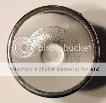
The reflector and glass window are held in the head by a threaded bezel. Unscrew the bezel and remove the reflector, glass window, and window o-ring. When reassembling, use caution to make sure the reflector slides around the emitter. If you are careless, you can tighten the reflector onto the emitter dome and scratch it. The window o-ring is also prone to squeezing out next to the window. If you see the o-ring sticking out, partially unscrew the bezel, and poke it back under the bezel.
Be careful when re installing the head that you don't smash the reflector into the LED leads. Some early failures were attributed to this problem. Since then the Golstons have come with a black plastic cover over the emitter star to protect the emitter leads.
The LED emitter is mounted to a star heat sink just like genuine Luxeons. The star is held to the resistor "can" by two phillips-head screws. The can is hollow. Earlier models have a can with a knurled edge that provides some grip when unscrewing the can. Later models including the 2 X 3.6V rechargeable models have a smooth edged can. On these models, the star and the end of the can are covered by a black plastic cap. This cap was installed to prevent contact between the reflector and the emitter leads. The black plastic cap is just glued on. Use the middle of a razor blade edge or similar edged tool and force the blade straight into the joint between the battery tube and the plastic cap. Break the adhesive joint all the way around, then use the blade to gently pry the cap up. If it does not loosen, use gentle turning pressure with a large pair of pliers to turn the cap. It is not threaded, so as soon as it turns, pull it straight off. If you ruin it, it's no big loss. Just be careful not to bottom-out the reflector onto the emitter leads.
The can is screwed into the battery tube. It may also be thread locked. If it is, use channel-locks to get just enough grip to break the sealant. It won't take much force at all. Unscrew the can. There is nothing further holding the can in.
On earlier models, there is a piece of small diameter plastic tube sticking out from the bottom. It extends into the battery tube to make contact with the batteries. There is a metal contact that the resistor lead is soldered to. The solder blob on the bottom hides the wire. On later models, including the 2 X 3.6V rechargeable models there is a PCB board on the bottom of the can with a solder blob in the center. The solder blob hides the resistor wire.
To remove the emitter and the resistor, unscrew the two Phillips head screws that hold down the emitter star. One screw will have a washer on it that is soldered to the negative contact on the star. Be careful not to damage the washer. It will remain on the star when you take the screw out. Desolder the positive wire and remove the star. There is nothing else holding it down. On the older model, desolder the blob on the battery contact and pull the resistor out. On newer models with the PCB board, you will have to take out the PCB to access the resistor. There is no printed circuit on the PCB to damage.
The PCB is held to the bottom of the can by several small crimps. This is where the aluminum edge has been smushed over the edge of the PCB. It may only have 3 crimps. Use a stout pair of needle nosed pliers to gently grip the edge and gently bend the smushed areas toward the outside. Then use a wooden skewer or another non-metallic object to gently push it out from the center hole on the emitter side. Angle the skewer toward the outside and try to push the board from the edges, not the center. It should come out without much coercion. Use light to firm pressure. It is possible to break the board. If it sticks, you may have to loosen the entire edge of the can.
The resistor on the later models is soldered to a short piece of wire coming from the battery contact solder blob. The resistor is held to the PCB by hot glue. More than one CPFer reported that the glue really stinks if it is burned. Clip the resistor leads near the resistor. Then scrape and cut the hot glue away using a razor blade or some other edged tool. Desolder the battery wire and remove the resistor.
To reinstall the PCB, use three or four SMALL dots of super glue on the very edges of the board. Don't use it all the way around, but more like a "chemical crimp". When batteries are installed, there will be pressure against the PCB holding it in the can. Super glue just makes the assembly firm, and will resist rotation. Keep adhesive away from the threads.
The tail cap switch can be taken apart easily using a pair of fine needle nosed pliers. Newer models including the 2 X 3.6V rechargeable model have a black plastic switch cover that has a spring loaded brass plunger sticking through as a battery contact. This is just a cover for the original switch underneath. This is necessary to extend the battery contact into the battery tube. Remember that the original Golston has an extension on the bottom of the emitter can. Later models don't so they have to make up the distance with a longer tail cap contact. If your light has the black plastic and brass switch cover, use needle nosed pliers in the two small holes like a key, and gently unscrew the cover. Once out, the tail cap will be identical to older models' tail cap.
The entire switch assembly including the spring will unscrew as one piece. Use the pliers to grasp the aluminum assembly using the notches in the sides. Carefully unscrew it. The rubber switch boot will fall out once the switch assembly is removed.
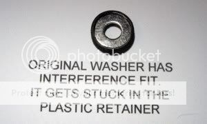
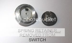
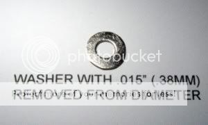
Disassemble the switch further by removing the spring assembly. There is a small battery contact spring held in by a plastic retainer. Use the pliers in the small holes in the plastic retainer to unscrew this retainer. The retainer will come out with the battery contact spring and a steel washer. The switch module will fall out once the spring assembly is removed. The switch cannot easily be taken apart. I don't recommend taking it apart.
Bernie
Also, please post pictures of whole flashlights, parts of them, mods, beamshots etc. I will cut and paste those that I find useful to illustrate my descriptions in the first several posts unless you indicate otherwise. The contributor will be cited in each case. NO HOTLINKING PLEASE per CPF rules.
Thank you,
Bernie
The whole head of the "Golston" family of lights unscrews from the battery tube. On some models, the head is held firm with thread locker. The thread locker is weak, and usually can be broken loose by hand. If necessary use a strap wrench on the bumpy part of the head just below the bezel. I am not aware that this has been necessary on any of these lights. Once the head is off, clean any hard sealant from the threads and o-rings. Use plastic or wooden tools to prevent damaging the finish or o-rings.
The reflector and glass window are held in the head by a threaded bezel. Unscrew the bezel and remove the reflector, glass window, and window o-ring. When reassembling, use caution to make sure the reflector slides around the emitter. If you are careless, you can tighten the reflector onto the emitter dome and scratch it. The window o-ring is also prone to squeezing out next to the window. If you see the o-ring sticking out, partially unscrew the bezel, and poke it back under the bezel.
Be careful when re installing the head that you don't smash the reflector into the LED leads. Some early failures were attributed to this problem. Since then the Golstons have come with a black plastic cover over the emitter star to protect the emitter leads.
The LED emitter is mounted to a star heat sink just like genuine Luxeons. The star is held to the resistor "can" by two phillips-head screws. The can is hollow. Earlier models have a can with a knurled edge that provides some grip when unscrewing the can. Later models including the 2 X 3.6V rechargeable models have a smooth edged can. On these models, the star and the end of the can are covered by a black plastic cap. This cap was installed to prevent contact between the reflector and the emitter leads. The black plastic cap is just glued on. Use the middle of a razor blade edge or similar edged tool and force the blade straight into the joint between the battery tube and the plastic cap. Break the adhesive joint all the way around, then use the blade to gently pry the cap up. If it does not loosen, use gentle turning pressure with a large pair of pliers to turn the cap. It is not threaded, so as soon as it turns, pull it straight off. If you ruin it, it's no big loss. Just be careful not to bottom-out the reflector onto the emitter leads.
The can is screwed into the battery tube. It may also be thread locked. If it is, use channel-locks to get just enough grip to break the sealant. It won't take much force at all. Unscrew the can. There is nothing further holding the can in.
On earlier models, there is a piece of small diameter plastic tube sticking out from the bottom. It extends into the battery tube to make contact with the batteries. There is a metal contact that the resistor lead is soldered to. The solder blob on the bottom hides the wire. On later models, including the 2 X 3.6V rechargeable models there is a PCB board on the bottom of the can with a solder blob in the center. The solder blob hides the resistor wire.
To remove the emitter and the resistor, unscrew the two Phillips head screws that hold down the emitter star. One screw will have a washer on it that is soldered to the negative contact on the star. Be careful not to damage the washer. It will remain on the star when you take the screw out. Desolder the positive wire and remove the star. There is nothing else holding it down. On the older model, desolder the blob on the battery contact and pull the resistor out. On newer models with the PCB board, you will have to take out the PCB to access the resistor. There is no printed circuit on the PCB to damage.
The PCB is held to the bottom of the can by several small crimps. This is where the aluminum edge has been smushed over the edge of the PCB. It may only have 3 crimps. Use a stout pair of needle nosed pliers to gently grip the edge and gently bend the smushed areas toward the outside. Then use a wooden skewer or another non-metallic object to gently push it out from the center hole on the emitter side. Angle the skewer toward the outside and try to push the board from the edges, not the center. It should come out without much coercion. Use light to firm pressure. It is possible to break the board. If it sticks, you may have to loosen the entire edge of the can.
The resistor on the later models is soldered to a short piece of wire coming from the battery contact solder blob. The resistor is held to the PCB by hot glue. More than one CPFer reported that the glue really stinks if it is burned. Clip the resistor leads near the resistor. Then scrape and cut the hot glue away using a razor blade or some other edged tool. Desolder the battery wire and remove the resistor.
To reinstall the PCB, use three or four SMALL dots of super glue on the very edges of the board. Don't use it all the way around, but more like a "chemical crimp". When batteries are installed, there will be pressure against the PCB holding it in the can. Super glue just makes the assembly firm, and will resist rotation. Keep adhesive away from the threads.
The tail cap switch can be taken apart easily using a pair of fine needle nosed pliers. Newer models including the 2 X 3.6V rechargeable model have a black plastic switch cover that has a spring loaded brass plunger sticking through as a battery contact. This is just a cover for the original switch underneath. This is necessary to extend the battery contact into the battery tube. Remember that the original Golston has an extension on the bottom of the emitter can. Later models don't so they have to make up the distance with a longer tail cap contact. If your light has the black plastic and brass switch cover, use needle nosed pliers in the two small holes like a key, and gently unscrew the cover. Once out, the tail cap will be identical to older models' tail cap.
The entire switch assembly including the spring will unscrew as one piece. Use the pliers to grasp the aluminum assembly using the notches in the sides. Carefully unscrew it. The rubber switch boot will fall out once the switch assembly is removed.
Disassemble the switch further by removing the spring assembly. There is a small battery contact spring held in by a plastic retainer. Use the pliers in the small holes in the plastic retainer to unscrew this retainer. The retainer will come out with the battery contact spring and a steel washer. The switch module will fall out once the spring assembly is removed. The switch cannot easily be taken apart. I don't recommend taking it apart.
Bernie
Last edited: