High current (SST-90) driver

DIWdiver

Flashlight Enthusiast
Joined
Jan 27, 2010
Messages
2,725
Location
Connecticut, USA
Hi everyone,

I have been ghosting this board for quite a while, and learning a lot, for which I am grateful. I finally think I may have something to contribute.

There seems to be a shortage of high current drivers for the newest high power LEDs. As a result of a recent conversation, I have designed a driver capable of up to 10A. I'm an engineer by profession and have built several LED drivers, but in the area of flashlights I'm a hobbyist. Since I don't need this driver myself, the question of whether it's worth building is more a question of whether folks would use it than whether I could make money. I'm posting now to see whether people would be interested in this driver if I built a few of them.

The characteristics would be:
Max current:10 A (or less if desired)
Max input voltage: 12V (16V available at higher cost).
Dual-level output: Selectable high/low output, via SPDT switch
Adjustable output: "high" output adjustable from 1A to 10A and "low" output adjustable from 1A to 2.5A by adding series resistors, 10A/2.5A with no resistors.
Size: 1.0 inch diameter by 0.35 inch thick
Heatsink: This is a linear regulator, so it will require heatsinking to protect from overheating. Connection to heatsink would be by one screw, #4, #6, 2.5mm or 3mm, or by thermal epoxy. Heatsink compound recommended if using screw.

This would be a 0-mode driver, meaning it's on whenever you apply power. There's no 'clicky' switch interface. The High/Low switch could have a center off position if you want to turn it off that way. The switch is low current, so it could be a miniature or subminiature switch, not necessary to handle the output current. The driver would be compatible with PWM boards I have seen.

This driver was originally intended for driving a single SST-90 at 7A from a 4-cell Ni-MH battery pack. Though it could be use over a wide range, it would be most efficient when the input voltage is 0.4 to 1.0 volts above the output voltage. With proper heatsinking , the driver could handle up to 30W dissipation, up to 100 watts output. Higher power levels could be made available if necessary.

If there's enough interest, I will make some of these, available at around cost, in the appropriate B/S/T area. If not, then I'm sorry to bother you.

D
 
As of now demand is high and supply is nill, so work on mate;)

Be aware that another similar project is ongoing and ahead of you by sector_cleared

:welcome:
 
Actualy there is antoher one in progress:
By FPPF

I am verry intrested in a driver wich allows me to driver 2 SST90's in series from a 4 series Li-Ion pack (nominal 14,8V max 16,8V).

For me dimming should be ideal via a potentio meter.

Greetz Johan
 
mhh, i linear regulator for a single sst-90 with a maximum input voltage at 12 volts? are you shure?

my calculations: the sst-90 have 4.0 volts forward voltage at 10 amps, so the regulator must must destroy 8 volts at 10 amps = 80 watt?!?

if you have 4 eneloops then they have 4.8 volt under load maybe a little less. 0.8 x 10 amps = 8 watt also to much for a portable flashlight.

just my two cents...

markus
 
Besides the other drivers in design now (mentioned above), I would be definitely be picking one of these linear regulators up. I have a 4 NiMh project already to go, but never finished it because of all the low resistance mods I did would :poof:the LED at full charge. I just didn't want to risk it with a $50 LED.
 
mhh, i linear regulator for a single sst-90 with a maximum input voltage at 12 volts? are you shure?

my calculations: the sst-90 have 4.0 volts forward voltage at 10 amps, so the regulator must must destroy 8 volts at 10 amps = 80 watt?!?

if you have 4 eneloops then they have 4.8 volt under load maybe a little less. 0.8 x 10 amps = 8 watt also to much for a portable flashlight.

just my two cents...

markus

Hi markus,

More or less, you are correct. The SST-90 all by itself is far to much heat for a hand held "flashlight" for regular use. The SST-90 already draws something like 4V x 10 A = 40 watts, so far above the more practical 15 - 20 watts max for heat generation.

With a linear regulator adding 10 Watts of heat per volt of battery voltage above the LED Vf, this adds up fast.

The 4 - 5 NiMH cells might be a practical use of this linear approach, but even 2 x Li type cells would force the user to wear gloves just with the driver's heat.

As a practical matter, a quality, efficient, reliable, inductor based current mode driver will have a hard time coming to market for much under $75-100 in hobby quantities, at least based on my simple spreadsheet of parts list and pricing. Anyone wanting to play with SST-90s with other than direct drive or resistor limiting for under $ 30 - 40 worth of even a crude driver will have few other options, at least IMHO.
 
I would pay 70 bucks for a good one.

If you build it, they will come.:)

At $70, I would make a killing (which would be cool, but is not my goal). They will be a lot less than that. I'm about ready to order prototype boards and parts.

Can you define good? I expect these will provide full current down to about 4.0V input, 3.6V output. They won't be well protected against surges, transients, ESD, or reverse battery voltage, so they won't be good for automotive applications (intended for battery applications) and could fail with careless handling, but should be pretty rugged once installed in a system. With sufficient heatsinking, they should survive shorted output for any duration.

D
 
Actualy there is antoher one in progress:
By FPPF

I am verry intrested in a driver wich allows me to driver 2 SST90's in series from a 4 series Li-Ion pack (nominal 14,8V max 16,8V).

For me dimming should be ideal via a potentio meter.

Greetz Johan

4s Li-Ion would be a lot of extra voltage for a linear driver, all of which would be wasted as heat. For that pack you'd be better off with one of the swithching drivers under development by other members.

For two LEDs in series. a 7s NiMH or 3s LiIon pack would be better with a linear driver. Even a 2s LiIon would be okay (and much more efficient), if it were acceptable that light output would begin to drop near end of battery life.

Dimming with a potentiometer would work well with my driver. 500K audio taper would be best, I think.

D
 
Interested! I can't contact you via PM...

I'm not sure why you can't PM me. I can't log into PM area either. Is that something that gets approved after you turn out to be a good member? I didn't see anything that suggested that in the rules.
 
Good for me would mean adjustable in some way thru the range, 5 to 12V input, high efficiency, setup/recall power up,& pwm input. :):)
 
I'm not sure why you can't PM me. I can't log into PM area either. Is that something that gets approved after you turn out to be a good member? I didn't see anything that suggested that in the rules.

Hi DIWdiver, I think you are right about there being some minimum number of posts / time for PMs to work.

Your idea is good for what it is, a linear driver. It will take some education for people to understand what this means, and the importance of balancing the input voltage, LED Vf, and thermal management. I routinely use resistors to manage LEDs (as well as more advanced drivers) but I understand the trade off. Sometimes, a resistor really is a good way to go.

Possibly a good place to start is to tell them to limit the battery voltage to no more than 2 volts higher than the LED Vf. I can just imagine someone attempting to use a 12 volt battery voltage with an LED with 4 Volts Vf, and then complaining about run time and heat generation at 10 amps. :candle:

Good luck with your project and please keep us updated.

BTW - this would be a good thread to have in the "electronics and battery" section, along with with several other current regulation circuits threads in this section. Perhaps a mod will consider this?
 
A boost driver would be nice ;)
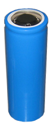
Driven by a single LiFePO4 cell that can deliver lots of current
4205.jpg


http://www.batteryspace.com/lifepo442120emsizecell32v10ah50arate32wh.aspx
 
Good for me would mean adjustable in some way thru the range, 5 to 12V input, high efficiency, setup/recall power up,& pwm input. :):)

Unfortunately, "High efficiency, 12V input", and "one LED, linear driver" are mutually exclusive.:(

Being a linear driver means that the input and output current are the same. The input voltage is dropped across a lossy element (like a resistor) to reach the desired current. A linear driver differs from a resistor in that the lossy element (a transistor) is constantly adjusted to keep the current constant. In a resistor, the value is fixed, so the current changes with input voltage changes.

To calculate the efficiency of a linear driver is very simple, and the equation will reveal a serious drawback of this type of driver:

Eff = Vout/Vin

From this you can easily see that the efficiency tanks as the input voltage goes up.

However, if you carefully match the input and output voltages, the efficiency can be quite good. For example, this driver was intended to be run at Vin of 4.0-4.8V and Vout of 3.6V (that's a 4-cell NiMH pack running one SST-90 at 9A). When the battery is fully charged, the efficiency is

Eff = 3.6/4.8 = 0.75, or 75%

That's not great, but not terrible. But watch what happens as the battery voltage falls. The efficiency rises to

Eff = 3.6/4.0 = 0.9, or 90%:)

On average, you'd expect something in the low 80's for percent efficiency. That's pretty respectable for a simple driver like this. But if you were to use 2 LiIon cells, efficiency would range from 43% to 49%. Not many users would be happy with that! In that case you'd really want a switching driver like some others are working on. With those you'd expect efficiencies of 85% and higher all the time. However those are more complex and likely more expensive.

As far as your other desires, there isn't anything to set up in this driver. There is a toggle switch input to turn on high or low setting. Settings can be adjusted down with an external resistor. A PWM input could be implemented, but I didn't include that. I could tell you how to do it externally if needed.

D
 
A boost driver would be nice ;)
Driven by a single LiFePO4 cell that can deliver lots of current

Yeah, that would be nice. Maybe in a while, if nobody else does it, and if my experience with this one is happy. However you'd need two LEDs in series to use a boost convertor off LiIon (because the output can never be less than the input voltage). Otherwise it would need to be buck-boost, which is more complex and less efficient.

You could boost off one or two NiMH cells...

D
 
Top