
cgpeanut
Enlightened
3
Kevin,
When I did the Q3 mod the wife took the digital camera so no pics on the q3 board and stupid me I potted it, I'm still looking for the digital camera /ubbthreads/images/graemlins/frown.gif
The IMS reflector is a bit taller than the stock reflector so you may want to shorthen that ring. But to be honest, I think the stock reflector is good enough, not much gain with the IMS and a lot more work. I wanted to replace the plastic lens that's why I did it.
I added a p-channel fet IRLML6401 for reverse polarity protection in the Q3 circuit, incase you place the R123 backwards it will prevent the uPIC from blowing.
DJ & I tested this feature, and it works, Placed the R123 in there for more than 30mins, flipped it back, no problem.
Also the LDO chips I used are in DCQ package like this:
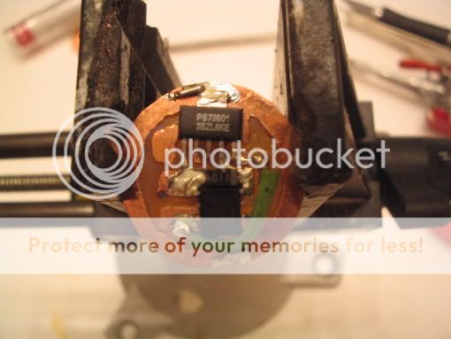
A lot bigger I wanted to use all the real estate in the Q3 board.. Pin outs are different from the sot-23's DJ sent you so component layout will not be the same.
Since the Q3 board is bigger /ubbthreads/images/graemlins/smile.gif you can place the components more to the center that way the aluminum ring sits flat.
Kevin,
When I did the Q3 mod the wife took the digital camera so no pics on the q3 board and stupid me I potted it, I'm still looking for the digital camera /ubbthreads/images/graemlins/frown.gif
The IMS reflector is a bit taller than the stock reflector so you may want to shorthen that ring. But to be honest, I think the stock reflector is good enough, not much gain with the IMS and a lot more work. I wanted to replace the plastic lens that's why I did it.
I added a p-channel fet IRLML6401 for reverse polarity protection in the Q3 circuit, incase you place the R123 backwards it will prevent the uPIC from blowing.
DJ & I tested this feature, and it works, Placed the R123 in there for more than 30mins, flipped it back, no problem.
Also the LDO chips I used are in DCQ package like this:
A lot bigger I wanted to use all the real estate in the Q3 board.. Pin outs are different from the sot-23's DJ sent you so component layout will not be the same.
Since the Q3 board is bigger /ubbthreads/images/graemlins/smile.gif you can place the components more to the center that way the aluminum ring sits flat.


")