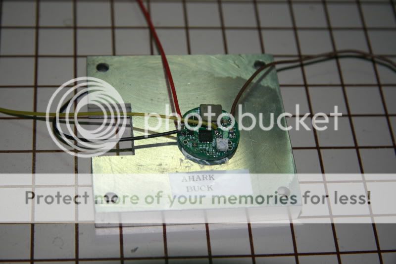
I have been able to get 4A on the input. The blue shark must be heatsinked properly and this means the gap between the copper C and the heatsink must be perfect. Any heatsink gap due to a thick layer of epoxy will not generate a proper heat transfer.
You are at the limit. I've seen improper setups fail at 3A input. With proper mounting you can get the optimum. It is hard to tell in the picture the actual contact thickness under the blue shark and thus, impossible to tell. But, in almost all cases I've seen the blue shark had a thick of gap between the copper C and heatsink.
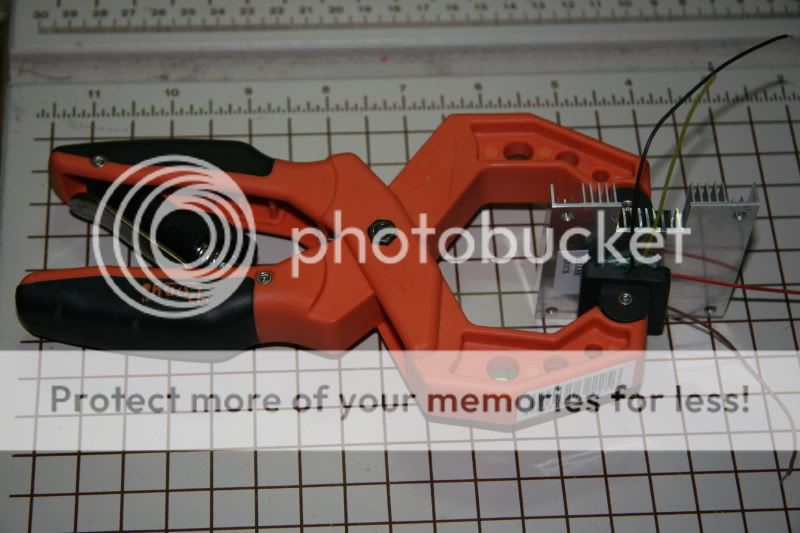
To properly attach the blue shark should more than likely be clamped the whole time the glue is setting up. Also, some people lap the bottom of the copper C to make it even flatter.
If you are just bench testing you can use a strong fan to keep the converter attached to a heat sink cool.
If you can avoid pushing the Shark to the extreme it is always recommended.
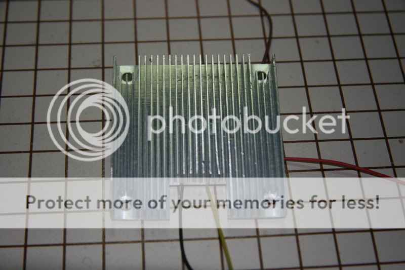
If your heatsink is only the dark rectangle that is not enough heat sink mass and if it is just sitting on the metal plate that is not a good contact to transfer from the dark plate to the sheet metal top.
Wayne
You are at the limit. I've seen improper setups fail at 3A input. With proper mounting you can get the optimum. It is hard to tell in the picture the actual contact thickness under the blue shark and thus, impossible to tell. But, in almost all cases I've seen the blue shark had a thick of gap between the copper C and heatsink.
To properly attach the blue shark should more than likely be clamped the whole time the glue is setting up. Also, some people lap the bottom of the copper C to make it even flatter.
If you are just bench testing you can use a strong fan to keep the converter attached to a heat sink cool.
If you can avoid pushing the Shark to the extreme it is always recommended.
If your heatsink is only the dark rectangle that is not enough heat sink mass and if it is just sitting on the metal plate that is not a good contact to transfer from the dark plate to the sheet metal top.
Wayne
Last edited: