Testing C/D cells in Maha C9000

Power Me Up

Enlightened
Joined
Mar 19, 2007
Messages
634
Location
Brisbane, Australia
Since there seems to be some confusion on how to connect C and D sized cells to a Maha C9000, I'll create this thread and include a photo of how I've done it:
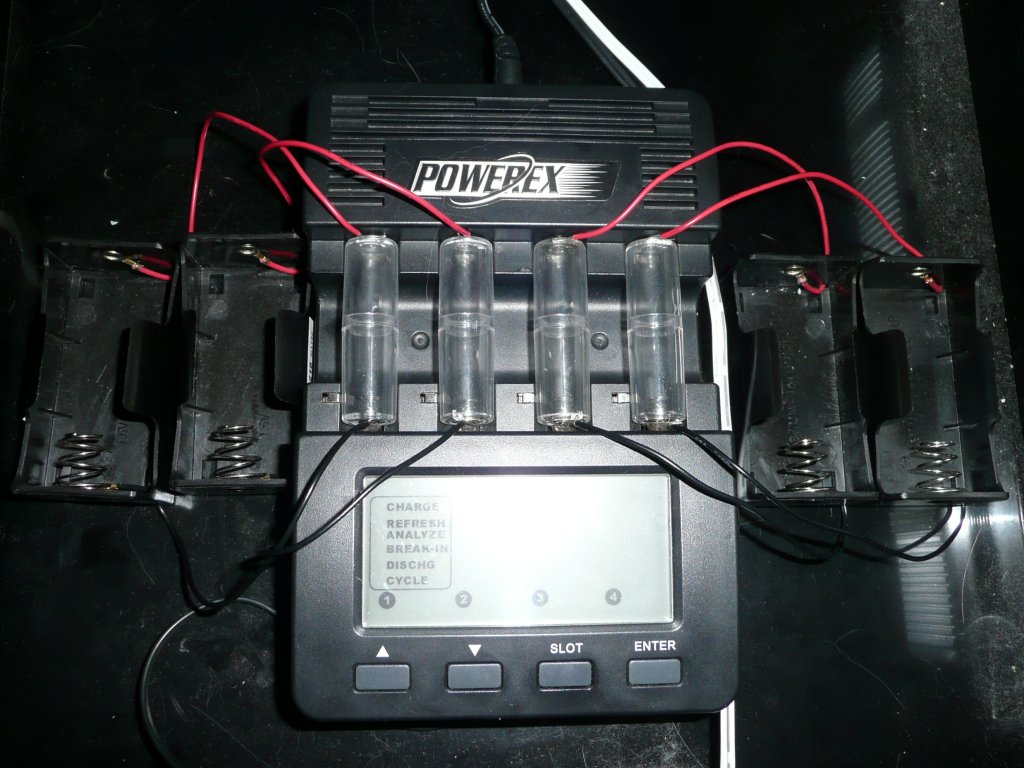
P1050788.jpg


Keep in mind that I'm using one of the earlier generation C9000 chargers that measures the cell voltage during the rest period instead of whilst the cell is under load - this pretty much eliminates the effect of the lead resistance.

The clear AA sized adapters that hold the leads in place came from DealExtreme:
http://www.dealextreme.com/details.dx/sku.3657

The C & D sized individual holders came from a local electronics store.

Feel free to post any questions!
 
you could certainly be right about that. at what rate do you charge 'em?

The charging that I did with the C9000 was at 2A - the charger did get very warm whilst charging them at that rate, so I just charge them on the C808M now. Besides that, it's also a bit of a hassle getting the adapters to hold the wires in place on the negative ends...
 
When it was described I thought you'd soldered the leads onto the battery adapter contacts. Actually, I thought you'd drilled holes in the plastic and had soldered the leads onto the INSIDE of the battery adapter thing.
 
I'm wondering why such a nice charger is limited to AA/AAA only -- seems to me there might be a pretty good market for a similar charger for C and D cells.
 

Many thanks again Power Me Up.

Incidentally, I just determined the break-in settings on my first edition MH-C9000 range from 500mAh to 20000mAh, so I'm hoping it will provide a proper break-in for NiMH and NiCAD cells within the same capacity range.

I plan to use it to at least exercise my C and D sized Eneloops providing they ever make it out of Japan.

I understand this cooling fan set-up utilized by coppertail will suffice to dissipate the additional heat away from the MH-9000:

http://www.candlepowerforums.com ... post1903127

Providing it's not larger than 35mm wide x 15mm deep, there's also room inside the charger directly below the upper-right ventilation slots for a 12 volt fan. It could probably even be powered from the adjacent DC input pins on the underside of the circuit board.
 
I'm thinking, if you're merely holding the leads against the charger contacts, properly-cut wooden dowels could be used if the adapters can't be found.
 
I'm thinking, if you're merely holding the leads against the charger contacts, properly-cut wooden dowels could be used if the adapters can't be found.

Although not something I would have anticipated either, wooden doweling isn't an ideal spacer or insulator:

In higher humidity areas and when charging at higher currents, I recommend using something other than wood. I found some wood spacers "leaking" when charging at 2 amps. This dielectric leakage was caused by the moisture content in the wood.

Plastic works great...

I had to modify my set up. I was charging at 2 amps and noticed that my wooden dowel was heating up. It must have picked up some moisture. I changed to plastic spacers and everything works fine now.
...
 
huh, so the wood was conducting? weird. Maybe if you baked it in an oven at 200F for an hour then shellacked it or something?
 
I think the idea of wood conducting enough to matter when used as a dummy cell in a charger is likely a case of drawing the wrong conclusion from the evidence. A damp piece of wood from natural air humidity is likely to have a resistance in the range of 100k to 1M. If we take an absolutely conservative worst case and suppose the resistance is as low as 1k or 1000 ohms then with the 1.5 volt charging voltage the current would be 1.5 mA.

We can calculate the power dissipation at this current from the formula (power) = (current squared) x (resistance). That would give 0.0015^2 * 1000 = 0.002 watts, or 2 mW. I couldn't therefore imagine significant heating to occur from electrical current.

What I think is more likely is that wood is a naturally "warm" material (it's basically a good thermal insulator and also a good holder of heat). Since the C9000 generates a lot of its own heat when charging at 2 amps I suspect the most likely explanation is that the wooden spacers warmed up from the heat of the Maha and then felt warm to the touch as a result.

Plastic spacers would not have the same ability to hold heat and transmit it to the human hand so they would feel cooler.
 
ok math smarty, can you calculate how much current would have to flow through the wood to warm it, say, to 100 degrees F? :p
 
ok math smarty, can you calculate how much current would have to flow through the wood to warm it, say, to 100 degrees F? :p
I sure can. ;)

First we need to estimate the rate of heat removal from the surface. To do this, we can assume a very conservative value of the natural convection film coefficient in air of 3 W/m2/K. (This is quite low; more likely values would be from 5-10 W/m2/K, but we want to assume a worst case scenario here.)

Next, we need the surface area for cooling. Since an AA cell is 14 mm diameter by 50 mm long, we get a surface area of:

A = pi/4 x 14^2 x 50 = 7700 mm^2 = 0.0077 m^2

Not all of this area is equally exposed for cooling since some of it is underneath or next to other spacers. To make a worst case estimate we will take only a quarter of this area, let's say 0.002 m^2.

You asked for our spacer to have a surface temperature of 100 F. I'm going to do the calculations in SI units since it works more conveniently with current and voltage, so that becomes 38 C. Let's assume the air temperature in the room is 20 C, which is an averagely comfortable 68 F.

We now find the heat loss from the spacer is estimated at:

Q = 3 W/m2/K x 0.002 m2 x (38 - 20) K = 0.1 W.

Next, we need to see how much current would generate 0.1 W of heat with a supply at 1.5 V. Since (power) = (current) x (voltage), we find the current would be:

I = 0.1 W / 1.5 V = 0.067 A.

Lastly, we need to see what resistance would produce a current of 0.067 A at 1.5 V. We find that by Ohm's law:

R = V / I = 1.5 / 0.067 = 22 ohms.

Having done the calculations, we then have to see what the answer means. It suggests that for a wooden spacer to heat up to 100 F by resistive heating from a 1.5 V supply, it would need to have a resistance no higher than about 20 ohms. In practice this is a very low resistance indeed, and unless the wood was impregnated with salt or some other conductive substance, it is extremely unlikely that it could have such a low resistance. We therefore presume that the use of wood for insulating dummy cells in a battery charger is not likely to be a problem. :thumbsup:
 
Last edited:
Hello Mr Happy,

Interesting...

Your numbers suggest that I was "kiln drying" my wooden dowels with the heat from the charger. It has been awhile since I set that up, but I seem to remember the dowels getting hotter than the charger was.

Perhaps higher humidity and close proximity to salt air contaminated my wood...

I spent a little time looking up the resistance of wood and it seems that it is dependent on the moisture content. At about 20% moisture, wood seems to have a low end resistance of around 1000000 ohms per cm. Since an AA cell is around 5 cm, a rather wet dowel would have a resistance of around 5000000.

I still think it is better to use plastic, but it appears that wood will also work.

Tom
 
Your numbers suggest that I was "kiln drying" my wooden dowels with the heat from the charger. It has been awhile since I set that up, but I seem to remember the dowels getting hotter than the charger was.
It may perhaps be that they felt hotter, but the actual temperature was similar to the charger? Sometimes the sense of touch can be misleading when comparing different materials. To be really sure of the situation I think one would need to use an infrared thermometer and measure the actual surface temperatures...

[Edit: I plan to use wood for some of my constructions since it is easy to obtain and easy to work with. I will report back if I come across any problems with that choice.]
 
Top