kosPap
Flashlight Enthusiast
Greetings all!
This will be a long read, so plan accordingly...
So a friend and I bought us a Kaidomain E6S 21700 flashlight each. Just because it is a P60 dropin compatible 21700 flashlight.
I have several dropins to go, but I had to built him a new one for this light.
He is doing SAR and firefighting work among other things, and we settled for an as-further-as-it-can-throw P60 reflector/LED combination.
At that point the Luminous SFT-40 was the best option, but being a dropin one cannot push on the amperage much.
I suggested a current around 4 amps, having in mind that I might have to mod a driver to this output..
I also decided to build a test dropin in parallel, that I would latter disassemble. So the story covers the making of both dropins actually.
But let's discuss the relevant P60 parts one by one.
Tools and Hardware
Older experimentation with 3Amp current mods, had shown me that I would have to upgrade the wiring testing devices I use.
For this build I upgraded the banana plugs on my DIY DMM leads. Now I feel I have a better connection in the DMM sockets.
The Flashlight Switch
As an "exercise in perfection", and since my friend has several forward click switches in his flashlights, I modded the flashlight with an original Fenix forward click switch.
That was a necessity cos the E6S uses a 16mm switch PCB. These cannot take a forward clickie, but I managed to installed the Fenix one with its rare 18mm PCB after some parts replacement.
Come on Kaidomain....There is enough room in the E6S tailcap, why not go for a larger PCB and switch? (the High Amp FWD ones need a 20mm PCB Only)
The P60 Dropin
For the dropin I used a FastTech sold XML one. This reflector works BEAUTIFULLY even for the XP-G, or similar, LEDs, giving maybe the tightetst beam of its kind.
Now there are more advanced dropins around, but my friend is a P60 junkie and there should be some back and forth combining them in hosts etc. So I stayed with classic style.
Since we are talking quite a lot of heat, I decided to try not gluing the MCPCB but instead solder it right on the brass pill.
It turned out to be easy. And did it on the first try. I tinted the MCPCB and the pill, added some solder flux and brought them together while heating with my soldering iron on High.
I soldered jumper wires to the led and fed it with a battery and a variable resistor to see. Well...it turned out that:
Problem no 1. The MCPCB was not centered
Problem no 2. The SFT40 does NOT focuses well on XML reflectors (this I knew beforehand having discussed LEDs over coffee with another flashaholic friend I visited with).
Problem no 1 was resolved by reheating the pill on a hot plate, and guiding it with tweezers, pressing through the wire holes. On an afterthought, this may not have been needed, since I think the solder tension would make the MCPCB self-center.
(in my amazement -and by close monitoring the temp- did not heat the assembly enough to affect the LED)
Problem no2 was resolved by grinding down the base of the reflector a bit. The SFT-40 should go higher in the reflector and one could try omitting the plastic centering plate.
I did so, using a DIY isolator over the wires taken from a dead 18650 battery.
But that caused problem no5 which I will cover towards the end.
The LED
So now I have the pill ready to accept the driver, but I opt to use a substitute 5A driver. Problem no3 arises.
Performance was disappointing! Too little output for an SFT40 on 5 amps!
Lots of head scratching and tests with my cool white LED...
More testing was done with the Dereelight DBS that takes dropins by screwing them on the reflector.
Measurements show that it wass better to use a regular SST-40, since in comparison one gets lots more lumens for a small loss in beam intensity only.
I decided to order a new SFT40. That added some wait to finishing the project.
I took me almost a month to find out what was going wrong...and that by accident, while reading an SFT40 High CRI review in another forum. Kaidomain had shipped me such a LED instead.
In hindsight I should have known 'cos the LED die color was too yellow to being a Neutral. But it was the first time I was using a SFT-40.

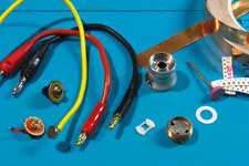
A Material's Descriptive Pic. Do notice the narrow bottom of the reflector that leaves a channel. The round white isolator fits there and protects the LED wires.
The brass pill shows the signs of a soldered MCPCB.
The thick DMM leads had a gold-plated bananas installed, and the yellow one has a magnet soldered, which helps with Amp draw measurements
the red driver is the Kaidomain P5000 and over it is the damaged Fenix switch.
The copper foil tape, the grinding wheel the SMD resistors and a regular trapezoid centering plate are also shown.
The Driver
I chose to use either the KAIDOMAIN P5000 or the Convoy 4-mode SST-40 driver.
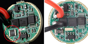
Info I had saved on the latter showed that it was 3amps out, later urgraded to 4 amps. And had saved the pic on the left. Notice the large SMD 010 resistor.
So when it came it was similar to what Convoy Official store now shows, it has a smaller 2106 020-value resistor.
I asked them and they said all are the same..
NOPE
Problem 4A. It was not 4amps as I thought, it is now SIX amps out (measured), not even 5 Amps as they now state.
6 amps to a P60 module, NO way! I would have to change the sense resistor.

Problem 4B. I had no resistors that I could combine to get the desired lower output. So ordered a whole bunch and waited some more.
Once I had the resistors I used a triple stack of, just to get a final 0.28 value. 0.05 - 0.13 - 0.13. Output was measured 3.7Amps, good enough for.
Final Assembly, Test and a Near Disaster.
All went fine, the module was assembled with a test reflector and isolator and was installed in the flashlight.
3.7 Amp got me 1000 lumens and more than 26000 Lux. Beam was fine.
So I removed the dropin from the flashlight, added the modded reflector, wrapped the dropin in copper tape and squeezed it in its pocket.
Installed a 21700 battery, turned the flashlight on and NO light. WTF?
I tried to remove the dropin and it as scorching hot! I mean I got a blister out if it!
Problem 5. Dangerous Short.
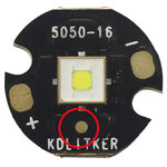
What happened was that the final isolator I installed was different that the test one, so the reflector made contact with a small, unusual + contact on the Kaidomain MCPCB.
The Convoy driver has a direct line from the center spring to the LED + side and ALL the power of the 21700 went through the whole body and made the springs take a set and melted the forward click switch on the ON position.

Fortunately the driver was OK, so I reworked on the flashlight by reinstalling the original switch, and grinding the reflector some more to make room for the regular 5050 die white isolator.
My last test was to make a "test burn" of the module. I left it on for a good time and I was monitoring output.
The driver has temperature regulation indeed. That is, output drops from full to 30% (medium mode) within 3 minutes. That is irrespective of what the lumen output is. Practically is a timer based stepping down.
So by downgrading the max output, medium mode changes too. Hmmmm...
One More Change on a Whim
The morning I was about to ship his flashlight and module I got the nerve to redo the module AGAIN!
I removed the SMD triple stack, and stacked two 050 resistors for a final value of 0.025 Ohms...
That brought the output to 4.2 amps, 1100 lumens and 32400 Lux out.
That's better.
Flashlight temperature got to 42ºC at the 3 minute mark and slowly rose to 52ºC 15 minutes later. Quite acceptable.
All is well now, and the flashlight will be used this evening at work, and my friend will get back to me.
Hopefully with no problems.
This will be a long read, so plan accordingly...
So a friend and I bought us a Kaidomain E6S 21700 flashlight each. Just because it is a P60 dropin compatible 21700 flashlight.
I have several dropins to go, but I had to built him a new one for this light.
He is doing SAR and firefighting work among other things, and we settled for an as-further-as-it-can-throw P60 reflector/LED combination.
At that point the Luminous SFT-40 was the best option, but being a dropin one cannot push on the amperage much.
I suggested a current around 4 amps, having in mind that I might have to mod a driver to this output..
I also decided to build a test dropin in parallel, that I would latter disassemble. So the story covers the making of both dropins actually.
But let's discuss the relevant P60 parts one by one.
Tools and Hardware
Older experimentation with 3Amp current mods, had shown me that I would have to upgrade the wiring testing devices I use.
For this build I upgraded the banana plugs on my DIY DMM leads. Now I feel I have a better connection in the DMM sockets.
The Flashlight Switch
As an "exercise in perfection", and since my friend has several forward click switches in his flashlights, I modded the flashlight with an original Fenix forward click switch.
That was a necessity cos the E6S uses a 16mm switch PCB. These cannot take a forward clickie, but I managed to installed the Fenix one with its rare 18mm PCB after some parts replacement.
Come on Kaidomain....There is enough room in the E6S tailcap, why not go for a larger PCB and switch? (the High Amp FWD ones need a 20mm PCB Only)
The P60 Dropin
For the dropin I used a FastTech sold XML one. This reflector works BEAUTIFULLY even for the XP-G, or similar, LEDs, giving maybe the tightetst beam of its kind.
Now there are more advanced dropins around, but my friend is a P60 junkie and there should be some back and forth combining them in hosts etc. So I stayed with classic style.
Since we are talking quite a lot of heat, I decided to try not gluing the MCPCB but instead solder it right on the brass pill.
It turned out to be easy. And did it on the first try. I tinted the MCPCB and the pill, added some solder flux and brought them together while heating with my soldering iron on High.
I soldered jumper wires to the led and fed it with a battery and a variable resistor to see. Well...it turned out that:
Problem no 1. The MCPCB was not centered
Problem no 2. The SFT40 does NOT focuses well on XML reflectors (this I knew beforehand having discussed LEDs over coffee with another flashaholic friend I visited with).
Problem no 1 was resolved by reheating the pill on a hot plate, and guiding it with tweezers, pressing through the wire holes. On an afterthought, this may not have been needed, since I think the solder tension would make the MCPCB self-center.
(in my amazement -and by close monitoring the temp- did not heat the assembly enough to affect the LED)
Problem no2 was resolved by grinding down the base of the reflector a bit. The SFT-40 should go higher in the reflector and one could try omitting the plastic centering plate.
I did so, using a DIY isolator over the wires taken from a dead 18650 battery.
But that caused problem no5 which I will cover towards the end.
The LED
So now I have the pill ready to accept the driver, but I opt to use a substitute 5A driver. Problem no3 arises.
Performance was disappointing! Too little output for an SFT40 on 5 amps!
Lots of head scratching and tests with my cool white LED...
More testing was done with the Dereelight DBS that takes dropins by screwing them on the reflector.
Measurements show that it wass better to use a regular SST-40, since in comparison one gets lots more lumens for a small loss in beam intensity only.
I decided to order a new SFT40. That added some wait to finishing the project.
I took me almost a month to find out what was going wrong...and that by accident, while reading an SFT40 High CRI review in another forum. Kaidomain had shipped me such a LED instead.
In hindsight I should have known 'cos the LED die color was too yellow to being a Neutral. But it was the first time I was using a SFT-40.

A Material's Descriptive Pic. Do notice the narrow bottom of the reflector that leaves a channel. The round white isolator fits there and protects the LED wires.
The brass pill shows the signs of a soldered MCPCB.
The thick DMM leads had a gold-plated bananas installed, and the yellow one has a magnet soldered, which helps with Amp draw measurements
the red driver is the Kaidomain P5000 and over it is the damaged Fenix switch.
The copper foil tape, the grinding wheel the SMD resistors and a regular trapezoid centering plate are also shown.
The Driver
I chose to use either the KAIDOMAIN P5000 or the Convoy 4-mode SST-40 driver.
Info I had saved on the latter showed that it was 3amps out, later urgraded to 4 amps. And had saved the pic on the left. Notice the large SMD 010 resistor.
So when it came it was similar to what Convoy Official store now shows, it has a smaller 2106 020-value resistor.
I asked them and they said all are the same..
NOPE
Problem 4A. It was not 4amps as I thought, it is now SIX amps out (measured), not even 5 Amps as they now state.
6 amps to a P60 module, NO way! I would have to change the sense resistor.

Problem 4B. I had no resistors that I could combine to get the desired lower output. So ordered a whole bunch and waited some more.
Once I had the resistors I used a triple stack of, just to get a final 0.28 value. 0.05 - 0.13 - 0.13. Output was measured 3.7Amps, good enough for.
Final Assembly, Test and a Near Disaster.
All went fine, the module was assembled with a test reflector and isolator and was installed in the flashlight.
3.7 Amp got me 1000 lumens and more than 26000 Lux. Beam was fine.
So I removed the dropin from the flashlight, added the modded reflector, wrapped the dropin in copper tape and squeezed it in its pocket.
Installed a 21700 battery, turned the flashlight on and NO light. WTF?
I tried to remove the dropin and it as scorching hot! I mean I got a blister out if it!
Problem 5. Dangerous Short.
What happened was that the final isolator I installed was different that the test one, so the reflector made contact with a small, unusual + contact on the Kaidomain MCPCB.
The Convoy driver has a direct line from the center spring to the LED + side and ALL the power of the 21700 went through the whole body and made the springs take a set and melted the forward click switch on the ON position.

Fortunately the driver was OK, so I reworked on the flashlight by reinstalling the original switch, and grinding the reflector some more to make room for the regular 5050 die white isolator.
My last test was to make a "test burn" of the module. I left it on for a good time and I was monitoring output.
The driver has temperature regulation indeed. That is, output drops from full to 30% (medium mode) within 3 minutes. That is irrespective of what the lumen output is. Practically is a timer based stepping down.
So by downgrading the max output, medium mode changes too. Hmmmm...
One More Change on a Whim
The morning I was about to ship his flashlight and module I got the nerve to redo the module AGAIN!
I removed the SMD triple stack, and stacked two 050 resistors for a final value of 0.025 Ohms...
That brought the output to 4.2 amps, 1100 lumens and 32400 Lux out.
That's better.
Flashlight temperature got to 42ºC at the 3 minute mark and slowly rose to 52ºC 15 minutes later. Quite acceptable.
All is well now, and the flashlight will be used this evening at work, and my friend will get back to me.
Hopefully with no problems.


