Jack Crow
Newly Enlightened
Hi all,
This has been a successful project. Made and given away many over the last couple of years.
The big problem with the stock lights is they eat batteries. Usually about 30 min and it's useless.
Made a battery adapter that allows the light to use a lithium123A cell (one time use). Had one run for over ten hours w/o diming out.
Let's see if the system will let me post some photos.
Not sure what happened, looks like the sequence of photos got reversed.
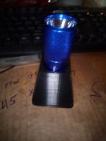
Anyhow the first photo is now the adapter in the light. Not tight nor snug. It will tip out if opened and turned.
Same for the battery in the adapter. Just a little bit of rattle.
The second photo is the light, a battery in the adapter, and the tail cap.
Left some rough holes for polarity indicators.
The center conductor is a 4-40 stainless screw with hex nut.
If there is interest, I can post the .stl (the file 3D printers use) so you can make up some of your own. I usually make them ten at a time.
This is not going to solve this lights other problems. The constant sketchiness of the internal contacts. Been thinking on that as well. Playing with the idea of electro plating a connection between the circuit board and the aluminum housing. Then doing it again on the tail cap's internal connections.
Clearly not worth the effort but deeply satisfying to make it all work as it should and defeat the plans of obsolesce.
Share a thought.
Jack Crow aka Radio Mike


This has been a successful project. Made and given away many over the last couple of years.
The big problem with the stock lights is they eat batteries. Usually about 30 min and it's useless.
Made a battery adapter that allows the light to use a lithium123A cell (one time use). Had one run for over ten hours w/o diming out.
Let's see if the system will let me post some photos.
Not sure what happened, looks like the sequence of photos got reversed.
Anyhow the first photo is now the adapter in the light. Not tight nor snug. It will tip out if opened and turned.
Same for the battery in the adapter. Just a little bit of rattle.
The second photo is the light, a battery in the adapter, and the tail cap.
Left some rough holes for polarity indicators.
The center conductor is a 4-40 stainless screw with hex nut.
If there is interest, I can post the .stl (the file 3D printers use) so you can make up some of your own. I usually make them ten at a time.
This is not going to solve this lights other problems. The constant sketchiness of the internal contacts. Been thinking on that as well. Playing with the idea of electro plating a connection between the circuit board and the aluminum housing. Then doing it again on the tail cap's internal connections.
Clearly not worth the effort but deeply satisfying to make it all work as it should and defeat the plans of obsolesce.
Share a thought.
Jack Crow aka Radio Mike