Well I think this will be my second or third post on here. Already I've learnt racks from trawling through various posts and I'd like to say a big thankyou to everyone who posts up their thoughts and shares their expertise.
I have a plan and before I start spending money I'd just like to run it by folks here for comment to see if there is anything I could learn and maybe do better.
The starting point for the project is a set of cateye abs 35 lights. The end result I'm looking for is 2 sets of lights that will be suitable for mountain biking on the trails here in North Wales
The starting point

Cateye ABS 35
Batteries = 2 x (6 Volt 3000mAH) = 36 Watt hours
Low = 15 watt flood = 2.4 hrs
Med = 20 watt spot = 1.8 hrs
High = 15 watt flood + 20 watt spot = 1 hr
Weights
Cateye abs 35 = total 1.15kg (approx)
2 x batteries = 0.75
2 x head units inc bulbs = 0.25kg
1 x cable set = 0.15kg
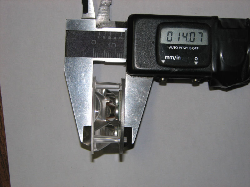
The bulb holder is the key element in this and here are a couple of photos


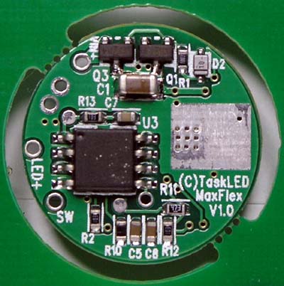
The plan is to split the system in two and create 2 lights from it. I'm intending to use the Cree MR11 from Cutter with the Maxflex driver.
Each light system will be like this

here's an incredibly dodgy drawing that shows how the led's, optics and driver should sort of fit into the head unit

This should give me 2 pretty good lights with usefull run times
LED Vf = 3 x 3.5 Volt LED's = 10.5 Volts
Battery = 6 Volt 3000mAH = 6 volts x 3 amps = 18 Watt hours
@ 1000mAH
1.0 amp x 10.5 Vf = 10.5 watt + 20% inefficiency = 13.125 watt draw
18 watt hours / 13.125 watt draw = 1.37 hour battery life
@ 750mAH
0.75 amps x 10.5 Vf = 7.875 watt - 20% = 9.84375
18 / 9.843 = 1.8 hour battery life
@500mAH = 2.75 hour battery life
@350mAH = 3.9 hour battery life
The weight should be in the half a kilo area
I'm planning of using one of these switches
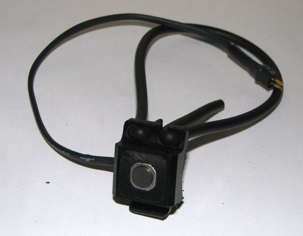
as made by the team thats put together the stunning Min-T. See here http://candlepowerforums.com/vb/showthread.php?t=172053&page=5
Queries I've got at the moment are
1. I don't know how deep exactly the LED & Optic assembly is including the board the LED's are mounted on
2. I'm going to mount the MCPCB onto a 42mm dia disk (made from an old trangia pan I think ) so that the bezel with hold all the optics in securely. This will either work perfectly or be a bit crap. How should I attach the disc to the mcpcb? Thermal epoxy (not actually sure what that is or where to get it:duh2
") or small bolts
or small bolts
3. how to secure the maxflex board in the housing so that it doesn't rattle around or short circuit. I've seen a photo of a board wrapped up in something to protect it and insulate it but not sure what it was. I guess its got to be heat resistant and non conductive.
These head units seem ideal for the purpose. I brought a replacement for a damaged one a year ago for £20. They are aluminium so should conduct and disipate heat pretty well. The mounting brackets for handle bars (inc oversize) work well (I also have a plan to adapt one to make a simple helmet mount) and spared are available
So then folks what do you think? any problems you can see?
All comments and opinions gratefully recieved
I have a plan and before I start spending money I'd just like to run it by folks here for comment to see if there is anything I could learn and maybe do better.
The starting point for the project is a set of cateye abs 35 lights. The end result I'm looking for is 2 sets of lights that will be suitable for mountain biking on the trails here in North Wales
The starting point
Cateye ABS 35
Batteries = 2 x (6 Volt 3000mAH) = 36 Watt hours
Low = 15 watt flood = 2.4 hrs
Med = 20 watt spot = 1.8 hrs
High = 15 watt flood + 20 watt spot = 1 hr
Weights
Cateye abs 35 = total 1.15kg (approx)
2 x batteries = 0.75
2 x head units inc bulbs = 0.25kg
1 x cable set = 0.15kg
The bulb holder is the key element in this and here are a couple of photos
The plan is to split the system in two and create 2 lights from it. I'm intending to use the Cree MR11 from Cutter with the Maxflex driver.
Each light system will be like this
here's an incredibly dodgy drawing that shows how the led's, optics and driver should sort of fit into the head unit
This should give me 2 pretty good lights with usefull run times
LED Vf = 3 x 3.5 Volt LED's = 10.5 Volts
Battery = 6 Volt 3000mAH = 6 volts x 3 amps = 18 Watt hours
@ 1000mAH
1.0 amp x 10.5 Vf = 10.5 watt + 20% inefficiency = 13.125 watt draw
18 watt hours / 13.125 watt draw = 1.37 hour battery life
@ 750mAH
0.75 amps x 10.5 Vf = 7.875 watt - 20% = 9.84375
18 / 9.843 = 1.8 hour battery life
@500mAH = 2.75 hour battery life
@350mAH = 3.9 hour battery life
The weight should be in the half a kilo area
I'm planning of using one of these switches
as made by the team thats put together the stunning Min-T. See here http://candlepowerforums.com/vb/showthread.php?t=172053&page=5
Queries I've got at the moment are
1. I don't know how deep exactly the LED & Optic assembly is including the board the LED's are mounted on
2. I'm going to mount the MCPCB onto a 42mm dia disk (made from an old trangia pan I think
) so that the bezel with hold all the optics in securely. This will either work perfectly or be a bit crap. How should I attach the disc to the mcpcb? Thermal epoxy (not actually sure what that is or where to get it:duh2 or small bolts3. how to secure the maxflex board in the housing so that it doesn't rattle around or short circuit. I've seen a photo of a board wrapped up in something to protect it and insulate it but not sure what it was. I guess its got to be heat resistant and non conductive.
These head units seem ideal for the purpose. I brought a replacement for a damaged one a year ago for £20. They are aluminium so should conduct and disipate heat pretty well. The mounting brackets for handle bars (inc oversize) work well (I also have a plan to adapt one to make a simple helmet mount) and spared are available
So then folks what do you think? any problems you can see?
All comments and opinions gratefully recieved
Last edited: