Is this a REAL Cree P4?

BatteryCharger

Flashlight Enthusiast
Joined
Jun 5, 2003
Messages
1,587
Location
The crazy guy next door
I bought the "regulated Cree P4" Xtar light from qualitychinagoods.com. They really should change their name to crappyworthlessgoods.com. Of course the light didn't work...so I took it apart. Can anybody tell if this is a REAL Cree P4 rather than a fake?

DSCF0021-1.jpg


And here's a pic of their magical regulating resistor. :rolleyes:
DSCF0015.jpg


If it is in fact a real P4, can I direct drive it with no resistor from an 18650 cell?
 

Marduke

Flashaholic
Joined
Jun 19, 2007
Messages
10,110
Location
Huntsville, AL
It doesn't have that little line/crack looking part on the bottom of the emitter in your picture like other Cree's I've seen.

Edit: Like this:
Cree2.jpg
 

mmmflashlights

Enlightened
Joined
Mar 24, 2007
Messages
345
Looks real but then counterfeit products have gotten good enough that you'd probably never have a way to know if it wasn't. QCG is a solid retailer in my experience, probably just got a dud.

Depending on the diameter of that 'circuit...', you could just take it as a good opportunity to replace it with a better one. Might not be easy though, depending on the size of the pill (looks really small from the photos) - I'd say it'd need to be at least 17mm wide and 10-12mm tall to fit most common circuits. Yes you could always just direct drive it with an 18650, I've done it with lights before and as long as the heatsinking is good it isn't too bad. It will heat up quickly though so a resistor or circuit would be better for long runtimes.
 

mmmflashlights

Enlightened
Joined
Mar 24, 2007
Messages
345
It doesn't have that little line/crack looking part on the bottom of the emitter in your picture like other Cree's I've seen.

Edit: Like this:

It just looks curved and faint in his photo from what I see, probably just the angle of the photo and the Cree's dome.
 

Luminescent

Enlightened
Joined
Jun 26, 2007
Messages
399
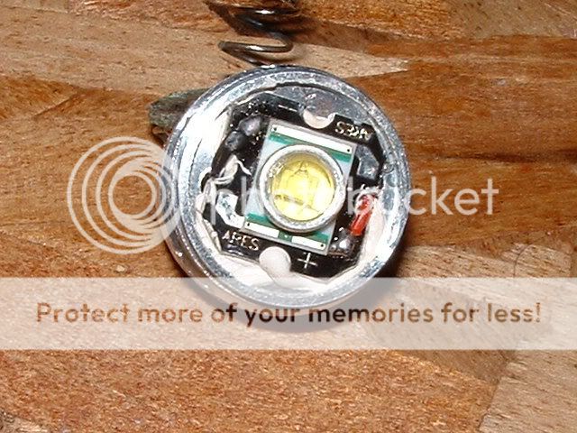
Looks like a P4. It's kind of hard to see in your photo, but it looks like your CREE is the newer type which has 4 bond wires. The newer CREE's with 4 bond wires should all be at least P4 bin or better as far as I know.

Grounding (or wiring shorts) are typically what screw up these lights, so if your light arrived dead, then I would check for these problems.

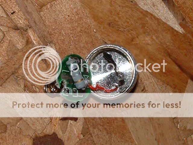
The resistor looks like Green/Black/Silver/Gold which is only a 0.5 ohm, so you are probably driving the emitter at about the right level already.

Calling a simple resistor a 'regulated' driver is indeed pretty sleazy (though technically the resistor does 'regulate' the current flow, just not in the sense of holding constant current drive).

I wouldn't mess with 'direct-drive'. Calling the Resistor a regulator is a joke, but Direct-Drive is a STUPID JOKE, dreamed up by know-nothing 'experts' who have no clue about how LED emitters need to be driven.

To get TRUE constant current drive (and safely drive the P4 at high current levels), DX has several 7135 based regulated boards that would work well.

DX has 7135 boards that run single output modes at 350ma, 700ma, 1050ma, and 1400ma.

The circuit is actually quite simple. Each 7135 chip gives 350ma of constant-current regulated drive to the LED emitter, and the higher output boards just have 2, 3, or 4 of these 7135 chips in parallel. If you get the 1400ma board it has 4 chips and you can enable/disable some of the chips to set 350ma, 700ma, 1050ma, or 1400ma. of drive.

DX used to sell these 7135 driver boards in single quantity, but now I can only find 10 and 20 qty packages on thier web site, so you might want to contact them to see if they can quote you a price for just 1 of the 1400ma driver boards.

http://www.dealextreme.com/details.dx/sku.1886


They do have a nice multi-mode 7135 board in single quantity. This board has multiple modes and drive levels with low/med/high/stobe/SOS settings with the high level at 1000ma (a high drive level for a P4, but should work well with good heatsinking).

http://www.dealextreme.com/details.dx/sku.6190

These 7135 boards can give TRUE regulated performance, with a nice consistant output level which will not change much in brightness as your battery starts to discharge.

To work well, these 7135 boards need to have a good solid mechanical connection around the perimeter of the circuit board to the flashlight body, which gives both electrical grounding and thermal heatsinking for the regulator chips.

You can search CPF and find quite a bit of info about these boards if you need more info.
 

mmmflashlights

Enlightened
Joined
Mar 24, 2007
Messages
345
Direct-Drive is a STUPID JOKE, dreamed up by know-nothing 'experts' who have no clue about how LED emitters need to be driven.

Uhh, that's a bit overboard. I myself said that it could be done, I'm not an expert but I'm not a 'know-nothing' without a clue either. No it's not the most ideal solution but he asked about it and if a traditional circuit cannot easily be fitted into the light then it is an option. I would try to avoid extended runtimes until the Cell's voltage has dropped to below 3.8V or so, and good heatsinking is going to be more important. As I said first and foremost, it would be a good opportunity to consider upgrading to a better circuit, however from looking at the photo I don't know that the pill is large enough for your typical-sized circuit.
 

BatteryCharger

Flashlight Enthusiast
Joined
Jun 5, 2003
Messages
1,587
Location
The crazy guy next door
It doesn't have that little line/crack looking part on the bottom of the emitter in your picture like other Cree's I've seen.
It actually does have that, just doesn't show up in the pic.


I can't tell why it didn't work, neg and pos were the best part of the circuit. Maybe the resistor was bad? I replaced it with a peice of wire, and it's running at about .9 amps with a 3.8v cell. Holy &$@* this thing is bright! I put in a fully charged cell and it went up to 1.6 amps, but I was afraid to use it for more than a second. Will it live at that many amps? It seems to be heatsinked rather well...
 

Luminescent

Enlightened
Joined
Jun 26, 2007
Messages
399
Uhh, that's a bit overboard. I myself said that it could be done, I'm not an expert but I'm not a 'know-nothing' without a clue either. No it's not the most ideal solution but he asked about it and if a traditional circuit cannot easily be fitted into the light then it is an option. I would try to avoid extended runtimes until the Cell's voltage has dropped to below 3.8V or so, and good heatsinking is going to be more important. As I said first and foremost, it would be a good opportunity to consider upgrading to a better circuit, however from looking at the photo I don't know that the pill is large enough for your typical-sized circuit.

First, I agree that the head looks a little small.

Kudo's to you, good catch on that one.

It's a good idea to verify the size of any driver, and it's not likely that there are going to be any off the shelf driver boards available for such a small mount. I believe that all the drivers I posted the links to are set up for the common 17mm sized mounting arrangements and may well be too large for the mount shown.

The 7135 chips themselves on the driver boards are really tiny and can be removed and mounted 'dead bug' style on a small custom board (I have done this for another light with little space), but this kind of surface mount device surgery (and the custom wireing needed to make it all work), is probably not something most folks will want to attempt.

Sorry if my comments offended you, but "Direct-Drive" is just flat out a bad idea for several reasons -

1. LED Vf varies from sample to sample, and LED's have a negative temperature coefficient (so when the temperature goes up their Vf goes down).

2. Battery voltage varies from cell to cell (and over the life of the battery), and chemical reactions in the battery electrolyte become more active when temperature goes up, raising available voltage and lowering internal resistance.

These things taken togeather cause the current to be VERY unstable when a lithium battery is 'directly driving' an LED emitter. First current flows and the LED heats up and VF drops, so the delta between the battery voltage and the LED Vf increases, which in turn makes the current increase more. In the mean time the battery is also heating up internally and it's resistance goes down and current goes up even more. The increased current heats the battery and LED up more, and off we go . . .

The purpose of an LED driver circuit is to provide a stable safe level of drive current to the emitter, and 'direct drive' will never be stable, and usually exceeds the safe level of drive current.

It's just flat out a bad idea.

I hate to say it, but given the space restrictions, the resistor shown may be the best solution.

If a meter is available, the tail cap of the light can be removed and the test leads bridged between the negative side of the exposed battery and the case of the light to measure the actual drive current.

Then the resistor could be replaced with lower values until the current increases to the desired drive level, but I wouldn't go much above 700ma. current drive or below about 0.2 ohms resistance (because you need a little resistance to offset the positive feedback mechanisms mentioned above).
 

mmmflashlights

Enlightened
Joined
Mar 24, 2007
Messages
345
Yes I'm familiar with thermal runaway. Yes I've run lights direct driven with an 18650 a number of times before and have measured the current. Yes I have witnessed the current slowly climb, especially at very high cell voltages. Yes I know what a circuit is for. No direct driving is not the ideal option as I said, but if you avoid long runtimes when the cell has a high voltage it can be used, I have not been at all clueless while directly driving a light. If you know that you'll need to use the light with it on for extended periods, then put the resistor back and use it in its stock form. A resistor is no real substitute for a decent regulating circuit (no regulation, poor efficiency, etc), but it will prevent high current levels to the LED for safe use in extended runtime. Do what suits your needs, with shorter runtimes DD is not a big issue, if you need to run the light continuously for extended time then you should either put a resistor in or a circuit. I don't often use Direct Drive anymore with my LEDs except some single 5mm LED lights where the biggest thing to worry about is shortening the life of a $.20 LED, but DD is an option if you understand the problems it can present. Whenever possible I try to replace a DD or resistored light with a circuit, mainly because I prefer regulated output and multiple output levels.
 
Top